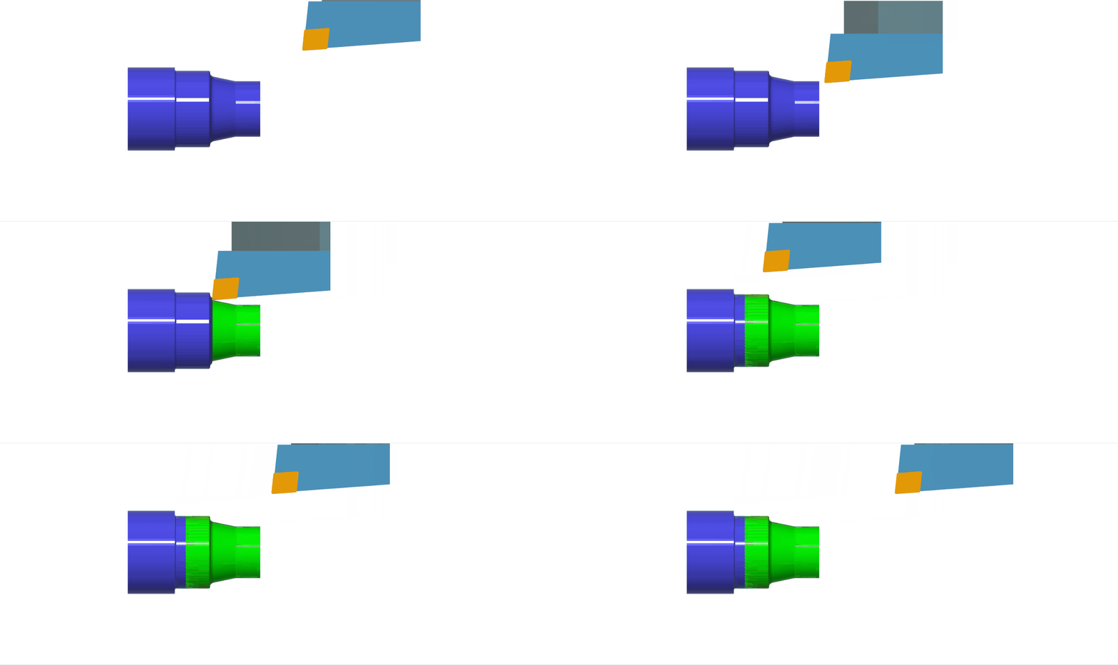
CNC turning is a subtractive manufacturing method (Removal of Material). Contrary to CNC Milling Lathe machining is for circular geometries (stock is commonly a solid/hollow cylinder) but a hexagon or square can be turned down to a cylinder. Instead of spinning the tools, a lathe will spin the stock material to a high rpm and then remove the material using a static tool. Unless a more complex system of live tooling or synchronous machine is happening(not covered). To create Lathe parts you create a CAM by making a series of tool paths that form your part. This page focuses on the toolpaths themselves for the Lathe. If you are starting your CAM, you must do some setup with your CAD model and the BIDC workholding. Watch this playlist of videos to begin your setup, then refer to this page to create the toolpaths for your part! Refer to the Lathe Tooling Guide to learn more about what each tool bit is called. To learn more about the workholding, and how your part will be clamped in the CNC mill while being machined, refer to the Workholding Guide.
Definitions
- Speed: How fast the stock spins in RPM (think S for Spin).
- CNC: Computer Numerical Control, refers to machines that are pre-programmed and controlled by computers, rather than manual control
- CAM: Computer-Aided Manufacturing, the software that allows you to program tool paths that control CNC machines. BIDC uses Fusion 360 for creating CAM.
- Toolpath: A pre-calculated path a tool will take to cut out a particular geometry.
- Chuck: The main work holding in Bechtel Lathes is a 3-jaw chuck.
- Tooling Note: Tools are organized by machine compatibility
- Cutting Presets: Each tool has all materials it can cut organized into categories
- N – Nonferrous, P – Steel, M – Stainless Steel, S – Superalloys, H – Hardened Materials
- See Material ISO grades to identify your material (anything from the stock room is usually aluminum N2 or mild steel P0)
Work Coordinate System
Unlike the mills where probing has to be done to find the center of your stock and also identify where your stock is. We align our stock on a center line in the work holding installed in the lathe and rely on our work coordinate system that we set up to try to match it as best as possible in real life. Our work coordinate system is set up in the CAM and is placed on the front of the lathe chuck(work holding) with the z-axis as the center line. Lathes tools travel along a center line so we only need to worry about the amount of length our stock sticks out by to create our part then. Our tools will then be probed to know the exact position that our bits stick out in and to know when our bits will make contact with our stock.
Main Operations
Facing: A facing pass smooths and squares the end of the workpiece by moving an OD (outer diameter) turning tool across the surface perpendicular to the workpiece’s axis. An 80-degree diamond insert is the preferred tool for this operation, as it provides an ideal cutting edge for consistent surface finishes.

Profile Roughing: The profile roughing pass shapes the workpiece along its contour, preparing it for a finishing pass by removing material in increments. This pass can be done on either the outer diameter (OD) or inner diameter (ID), depending on the required profile.

Setup:
- Tool Selection: Choose any OD or ID turning tool as required. If you’re using an ID tool, ensure there’s a pre-existing hole for the tool to enter and adjust the Mode setting to Inside Profiling.
- Feed & Speed: Enable Constant Surface Speed to maintain a steady chip load on the tool, which enhances tool life and ensures consistent cutting performance.
Geometry and Offset Adjustments:
- For Parting Off: If you plan to part off a section, set the Geometry option to Back – Model Back with a small negative offset. This positioning ensures clean cuts without excess material at the boundary.
Additional Settings:
- Grooving Operations: If deeper features require grooving operations, set Grooving to Don’t Allow Grooving to restrict the tool to contouring, not groove cutting. This configuration ensures cleaner profiling along deeper sections.
- Stock to Leave: Activate Stock to Leave to retain material for the finishing pass. Set X Stock to Leave to the minimum depth of cut, allowing for a smooth final contour, and set Z Stock to Leave to the facing depth of cut for uniform material removal during facing.
Executing the Pass:
- Left-Handed Tool Setup: If using left-handed tools for back-turning operations, set the direction to Back to Front to ensure optimal stability and cut quality when working from the rear of the workpiece.
- Pass Direction: Choose Front to Back direction for standard forward profiling, suitable for right-handed tools.
Profile Finishing: A profile finishing pass refines the workpiece along its contour, creating a smooth, accurate surface that matches the desired final shape. This pass is suited for both outer diameter (OD) and inner diameter (ID) finishing operations.

Setup:
- Tool Selection: Use any OD or ID turning tool, with a 30-degree diamond insert preferred for its precision on fine profiles. For ID finishing, make sure to switch the Mode to Inside Profiling to maintain accuracy within internal contours.
- Feed & Speed: For an improved surface finish, lower the Feed Per Revolution to 50-75% of the default value. This adjustment reduces tool pressure, allowing for finer cutting details. Enable Constant Surface Speed to maintain an even chip load, supporting a consistent finish.
- Left-Handed Tools: For back-turning with left-handed tools, switch the direction to Back to Front. This configuration supports a stable and accurate cut along the profile.
- Pass Direction and Tool Orientation: Pass Direction: Set the Direction to Front to Back for standard profiling, ideal for right-handed tools.
- Linking Adjustments: Resolving Linking Warnings: If a linking warning appears, adjust the Lead-Out settings. Disable Same as Lead-In and/or increase the Linear Lead-Out Angle to 90 degrees. These adjustments ensure smooth tool exit paths and prevent tool deflection at the end of the cut.
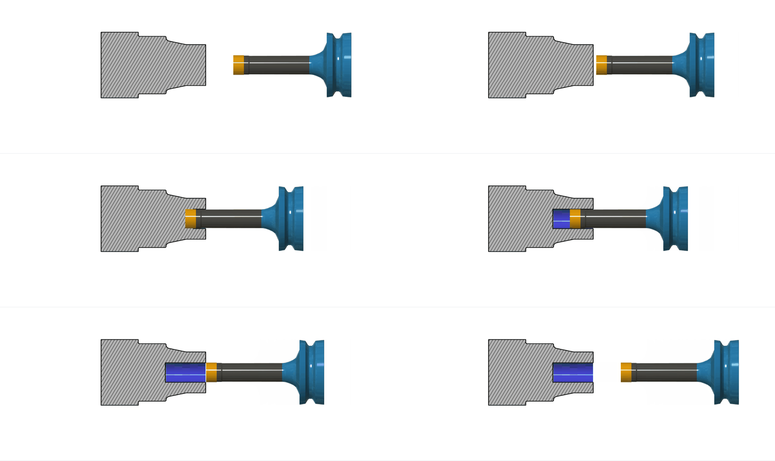
Drilling: Drilling operations on the Haas ST20 lathe are essential for creating precise holes in the workpiece, with adjustments for depth, clearance, and counterboring. The following settings ensure accurate hole placement and consistent results.

Setup:
Speed & Feed: The lathe’s maximum RPM is 4,000, so make sure to recalculate Speeds and Feeds accordingly to avoid exceeding this limit. Lower speeds can help control cutting temperatures and prevent tool wear.
Tool Selection: Choose a drill with the desired diameter, selecting the shortest length necessary to reach the required hole depth. This minimizes tool deflection and ensures a cleaner cut. Additional drill sizes are available at the Bechtel Center if needed.
- Grooving
- Tool: largest grooving bar for your desired geometry
- Talk to a Peer Mentor for inside grooving operations, they’re tricky
- Under Feed & Speed, enable [Use Constant Surface Speed]
- Geometry: Offset the [Front] and [Back] containment planes to focus only on the grooves you want to cut
- Enabling Rest Machining may reduce cycle time
- Passes: [Up/Down Direction] = [Only Down]
- Enable [Roughing Passes] and ensure [Maximum Roughing Stepover] is 80% of the tool width
- Tool: largest grooving bar for your desired geometry
- Part Off
- Tool: Part off blade (or grooving bar) with enough reach
- If there is no tool with enough reach, cut a groove and follow it on the vertical bandsaw
- Under Feed & Speed, enable [Use Constant Surface Speed]
- Geometry: Enable [Edge Break] and set [Chamfer Width] to a desired value
- If you are going to flip the part and cut the other side, add a negative offset from Model Back
- Radii: Set the [Distance to Cut Below Inner Radius] to [0.05]
- Passes: Enable [Use Reduced Speed and Feed], set the corresponding radius to [0.25 in], ensure the corresponding feed rate is 25% of the normal feed rate
- Enable [Allow Rapid Retract]
- Tool: Part off blade (or grooving bar) with enough reach

