| Problem statement Solution video |
NOTE: Please use F = 200 N in your calculations. The problem statement provided here has been modified to reflect this change in the value of F to be used.
DISCUSSION THREAD

Ask your questions here. Or, answer questions of others here. Either way, you can learn.
DISCUSSION and HINTS
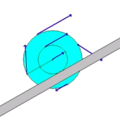
The animation below shows the motion of the wheel as it is being pulled up the incline. The animation shows the velocity of a number of points on the wheel. Think about the location of the instant center for the wheel as it rolls without slipping, and how this location affects the direction and magnitude of the velocities shown here.
Recall the following four-step plan outline in the lecture book and discussed in lecture:
Step 1: FBDs
Draw a free body diagram (FBD) of the wheel.
Step 2: Kinetics (Newton/Euler)
- Looking at your FBD above, which forces, if any, do work that is not a part of the potential energy of the system? Pay particular attention to the friction force at the no-slip point on the wheel - does it do work? How do you find the work done by the applied force F?
- Write down the kinetic energy of the wheel. Recall that the expression the KE for the planar motion of a rigid body is: T = 0.5*m*vA2 + 0.5*IA*ω2, where A is either the center of mass or a fixed point (fixed points include instant centers). So, in this case you can use either O or the no-slip contact point (let's call that point C).
- Define your gravitational datum line. Write down the potential energy for the wheel.
Step 3: Kinematics
Use the IC approach to relate the velocity of the point on the wheel where the cable comes off (call that point A) to the angular velocity of the wheel. Or, instead, use the following rigid body kinematics equation:
vA= vC + ω x rA/C
Through a time integration of the relationship between the speed of A and the angular velocity of the wheel, you can determine the distance through which F moves.
Step 4: Solve
From your equations in Steps 2 and 3, solve for the angular velocity of the wheel at position 2.
I keep getting that the square of angular velocity is negative. The NC work is less than the potential energy gained for me which makes my kinetic energy negative...
I think that you are not calculating the work done by F correctly. What is the numerical value for your work term?
My work term is 300 Nm. I got that the wire travels 3/2 d.
OK, I see the problem. Let's change the value of the applied force to F = 200 N. The problem statement linked above has been updated to reflect that change.
Thank you for bringing this to our attention.
Sorry just saw force was changed to 200.
Since gravity is not shown in the problem, can we assume it's in the horizontal plane and disregard potential energy due to gravity?
The problem is intended to be in a vertical plane. Please include gravity. The problem statement has been modified to include this.
Thanks for bringing this to our attention.
How is the fact that the force traveling 3/2d gotten? If you are comparing velocities around the IC of the disk, would it not be 3d is the distance the force travels?
From my understanding if point C is the contact point, G is the center of Gravity, and A is where the force F is acting then Va=3/2 wr and Vg=1/2 wr. So I would agree that F travels 3d and not 3/2d.
I believe it should be 3/2 d. This is because we are going off of the distance between the point and where it is rotating. In this case that would be the R to the center and the R/2 to the point of rotation.
Do we use the fact that the no slip part is the instant center for the wheel to find the distance F is pulled through?
Yes. That is the basis of what Malaika writes above.
Does the no slip condition imply that a friction force should be included in this problem?
Recall from the discussion in lecture that a friction force acting at a "no slip" cannot do work. If a force does not do work, it will not appear in the work/energy equation.
For the moment of inertia equations, would we place the radius r with the radius of gyration value k?
Recall that the mass moment of inertia about point O of a body with a mass of "m" and radius of gyration "k_O" is (by definition):
I_O = m*k_O^2
(Let me know if I am not answering your question.)
We also add another term to I due to Parallel Axis Theorem right? So I = m*k_O^2 + m*(R-r)^2? Please correct me if I'm wrong.
I believe the radius of gyration takes everything into account, so the parallel axis theorem is not necessary.
I'm not sure. The radius of gyration seems to be explicitly for rotation about O, while the wheel here is rotating about the point of no slip. I think we will need the parallel axis theorem.
It depends. If you choose O as your reference point, then no. If you choose the no-slip point as the reference point, then yes.
If I work with the moment of inertia at point C, the no slip point, do I put into account of the friction force for non conservative work?
Please see CMK comment above - remember that at a no slip point the frictional force cannot do work so that value is zero
Since this is a coil around o does this mean we need to use arc length instead of just the distance?
Since the force applied through the rope is constant, all you need to know is how far it travels, which you can determine by comparing the circumference of the small disk and large disk. The distance d will be covered by the small disk, so using the radius ratio you can determine how much rope is used at the large disk.