All posts by CMK

Homework H5.E - Sp 25

Problem statement
Solution video

https://youtu.be/rkIKCA_7Oic


DISCUSSION THREAD

Ask your questions here. Or, answer questions of others here. Either way, you can learn.


DISCUSSION and HINTS
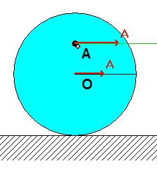
A cable connects block B to point A on the interior of the disk. We want to know the angular acceleration of the disk on release from rest. Watch the animation of the motion of the disk. What do you see in terms of the relationship between the accelerations of points O and A at the instant of release? And, between the accelerations of points A and B?

Recall the following four-step plan outline in the lecture book and discussed in lecture:

Step 1: FBDs
Draw individual free body diagrams (FBDs) of the disk and block.

Step 2: Kinetics (Newton/Euler)
Note that the no-slip contact point C will have, at most, an acceleration that points toward O. Because of this, we can use the following Euler equation for the disk: ΣMC = ICαdisk.

Step 3: Kinematics
Since the Newton equation for the block requires us to relate the acceleration of block B to the angular acceleration of the disk through point A on the disk, we should use the following rigid body kinematics equation:

aA= aC + αdisk x rA/C - ωdisk2rA/C

where we know that the horizontal component of acceleration of the no-slip contact point C is zero.

Step 4: Solve
From your equations in Steps 2 and 3, solve for the angular acceleration of the disk.

Homework H5.F - Sp 25

Problem statement
Solution videohttps://youtu.be/xVRtYNh2LhM

DISCUSSION THREAD

Ask your questions here. Or, answer questions of others here. Either way, you can learn.


DISCUSSION and HINTS
Link OA is pinned to ground at O. Slider B is constrained to move along a straight guide. Link AB, having negligible mass, connects point A on OA with slider B. With OA initially rotating CCW, and with a force F acting to the right on B, we want to know the initial acceleration of slider B.

Recall the following four-step plan outline in the lecture book and discussed in lecture:

Step 1: FBDs
Draw individual free body diagrams (FBDs) of the OA and slider B. Note that since link AB has negligible mass and that it has forces acting at only two points, AB is a two-force member. Knowing that, what are the directions of the reaction forces on OA and on B due to link AB?

Step 2: Kinetics (Newton/Euler)
You need to use an Euler (moment) equation for link OA, and a Newton equation for slider B.

Step 3: Kinematics
At the instant shown, the velocity of A is in the same direction as the velocity of B. What does this say about the instant center of AB, and therefore about the angular velocity of AB?

You will need two acceleration equations: one for link OA, and one for link AB:

aA = aO + αOA x rA/O - ωOA2 rA/O
aA = aB + αAB x rA/B - ωAB2 rA/B

Please note that ωOA is NOT known to be constant. Do not assume so. Combining the above kinematics equations will provide you with the relationships relating αOA, αAB and aB.

Step 4: Solve
From your equations in Steps 2 and 3, solve for the acceleration of the slider B.

Homework H5.C - Sp 25

Problem statement
Solution video

https://youtu.be/EFm9SObfGKA


DISCUSSION THREAD

Ask your questions here. Or, answer questions of others here. Either way, you can learn.


DISCUSSION and HINTS
There are two critical issues involved in solving this problem.

  • One, is starting out with good free body diagrams. Recall from our lecture discussion that the Newton/Euler equations typically prefer INDIVIDUAL FBDs. Note this in the discussion of Step 1 below.
  • Second, we need to be careful on signs in establishing our kinematics relating the acceleration of the two blocks to the angular acceleration of the pulley.

Recall the following four-step plan outline in the lecture book and discussed in lecture:

Step 1: FBDs
Draw individual free body diagrams (FBDs) of the pulley and the two blocks. A single FBD of the entire system will not be useful here. Let's say that we employ a "standard" xy-coordinate system (with x to the right and y up) for all FBDs.

Step 2: Kinetics (Newton/Euler)
You will need an Euler (moment) equation of the pulley about point C. In addition, write down the Newton equations for the y-motion for each of the two blocks. Write down all three equations using the sign convention discussed above.

Step 3: Kinematics
Here is where we need to be careful with signs. Write down the rigid body kinematics equations relating the accelerations of A and B back to the pulley center C:

aA = aC + α x rA/C - ω2rA/C
aB = aC + α x rB/C - ω2rB/C

This pair of equations will provide you with the relationships among aA, aB and α. Take note of the signs involved in these equations.

Step 4: Solve
From your equations in Steps 2 and 3, solve for the angular acceleration of the pulley and the accelerations of the two blocks.

Homework H5.D - Sp 25

Problem statement
Solution video

https://youtu.be/NTuAy-7KsLA


DISCUSSION THREAD

Ask your questions here. Or, answer questions of others here. Either way, you can learn.


DISCUSSION and HINTS
A horizontal force is applied to the center of mass of the thin bar, with the bar attached to a block that is constrained to have horizontal motion. Here want to know the resulting angular acceleration of the bar.

Recall the following four-step plan outline in the lecture book and discussed in lecture:

Step 1: FBDs
Draw individual free body diagrams (FBDs) of the bar and block.

Step 2: Kinetics (Newton/Euler)
Take care with your Euler (moment) equation. The point about which you write down the moment must be either the center of mass or a fixed point. For example, you can NOT write ΣMA = IAαAB  because A is neither a fixed point nor is it the center of mass.

Step 3: Kinematics
End A of the bar is constrained to move only in the horizontal direction. Since the Newton equation for the bar requires the usage of the acceleration of the center of mass G, you will also need to use a kinematics equation relating the acceleration of A to the acceleration of G:

aG = aA + α x rG/A - ω2rG/A

Combining the above kinematics equations will provide you with the relationships among aGx, aGy, aA and α.

Step 4: Solve
From your equations in Steps 2 and 3, solve for the angular acceleration of the bar.

Homework H5.A - Sp 25

Problem statement
Solution video

https://youtu.be/unjWjzAE7b0


DISCUSSION THREAD

Ask your questions here. Or, answer questions of others here. Either way, you can learn.


DISCUSSION and HINTS
With the length of cables AC and BD being the same, and with the cables being parallel for all motion, bar AB remains horizontal as it moves. Specifically, ωAB = 0 for ALL time, and therefore αAB = 0 always. (Note that ωAB = 0 does not necessarily say that αAB = 0, only if ωAB = 0 for all time.) Do you see this in the animation?

Since the center of mass for the bar is not equally spaced between points A and B, the tensions in the cables are not the same. You can see this in the animation below.

Recall the following four-step plan outline in the lecture book and discussed in lecture:

Step 1: FBDs
Draw a free body diagram (FBD) of the bar.

Step 2: Kinetics (Newton/Euler)
Take care with your Euler (moment) equation. The point about which you write down the moment must be either the center of mass or a fixed point. For example, you can NOT write ΣMA = IAαAB  because A is neither a fixed point nor is it the center of mass.

Step 3: Kinematics
As discussed above, bar AB remains horizontal for all motion. What does the say about the path of the center of mass G of the bar? And, from that, what is the direction of the acceleration of G, aG, at this instant?

Step 4: Solve
From your equations in Steps 2 and 3, solve for the tensions in the two cable. Your equations will contain three unknowns: TAC, TBD and aG.

Homework H5.B - Sp 25

Problem statement
Solution video

https://youtu.be/a0EJn-XhJLY


DISCUSSION THREAD

NOTE: Please leave your final answer in terms of variables defined in the problem, such as: M, m, g and ι. Also, the bar moves in a VERTICAL plane.

Ask your questions here. Or, answer questions of others here. Either way, you can learn.


DISCUSSION and HINTS
The motion of the bar is constrained by the two horizontal and vertical guides for the ends of the bar. These constraints add to the complexity of the kinematics (Step 3) of your solution, as we will discuss below. Take particular note of the direction of the acceleration of the center of mass G of the bar as it moves.

Recall the following four-step plan outline in the lecture book and discussed in lecture:

Step 1: FBDs
Draw a free body diagram (FBD) of the bar.

Step 2: Kinetics (Newton/Euler)
Take care with your Euler (moment) equation. The point about which you write down the moment must be either the center of mass or a fixed point. For example, you can NOT write ΣMA = IAαAB  because A is neither a fixed point nor is it the center of mass.

Step 3: Kinematics
End A of the bar is constrained to move only in the vertical direction. The other end of the bar (let's call it B) is constrained to move only in the horizontal direction. The first part of your kinematics should be directed to relating the motion of A and B through the rigid body acceleration equation:

aB = aA + α x rB/A - ω2rB/A

Since the Newton equation for the bar requires the usage of the acceleration of the center of mass G, you will also need to use a kinematics equation relating the acceleration of either A or B to the acceleration of G. For example, you could use:

aG = aA + α x rG/A - ω2rG/A

Combining the above kinematics equations will provide you with the relationships among aGx, aGy and α.

Step 4: Solve
From your equations in Steps 2 and 3, solve for the reactions NA and NB acting at ends A and B of the bar.

Homework H4.U - Sp 25

Problem statement
Solution video


DISCUSSION THREAD

Discussion and hints:

Recall that for oblique impact problems, it is recommended that you use three FBDs: A alone, B alone and A+B together. A+B together allows us to make the impact force internal (and not appear in the linear impulse-momentum equation). FBDs for A and B individually allows us to determine the t-direction components of velocity each for A and B.

Step 1: FBDs
Draw FBDs of A, B and A+B.
Step 2: Kinetics (linear impulse/momentum)
Consider using the linear impulse-momentum equation for the t-direction for A and B individually, and in the n-direction for A+B. You need four equations to determine the two components of velocity for each of the two particles. Consider the coefficient of restitution as your fourth equation.
Step 3: Kinematics
Step 4: Solve
Solve for the two components of velocity for each of the two particles. From these, the post-impact direction angles of motion can be found.


Any questions?

Homework H4.V - Sp 25

Problem statement
Solution video


DISCUSSION THREAD


Discussion and hints:

For this problem, make your system big. In your FBD include A, B, P and link AOB. With this choice, you can simplify your angular impulse-momentum analysis since you do not need to deal with the impact force between P and A since it will be internal to this system.

Step 1: FBDs
Draw an FBD of A, B, P and AOB together.
Step 2: Kinetics (angular impulse/momentum)
Consider the external forces acting on your system in your FBD. Which, if any, forces cause a moment about the fixed point O? Write down the angular momentum for each particle individually and add together to find the angular momentum for your system: HO = 2m rA/O x vA + m rB/O vB + m rC/O x vC. Is this momentum conserved? Also, consider using the coefficient of restitution equation.
Step 3: Kinematics
Use the rigid body velocity equation to relate the velocities of A and B.
Step 4: Solve
Use your results from Steps 3 and 4 to solve for the angular speed of AOB.


Any questions?

Homework H4.S - Sp 25

Problem statement
Solution video


DISCUSSION THREAD

Ask and answer questions here. You learn both ways.


DISCUSSION and HINTS

Recall the definition of angular momentum of a particle P (of mass m) about a fixed point O:  HO = m rP/O x vP.

For this problem, use this equation to find the angular momentum of the particle about the three fixed points A, B and C. Are any of these three values zero? If so, why does it equal zero?

Homework H4.T - Sp 25

Problem statement
Solution video


DISCUSSION THREAD

Ask and answer questions here. You learn both ways.


DISCUSSION and HINTS

Recall the following four-step plan outline in the lecture book and discussed in lecture:

Step 1: FBDs
Draw a free body diagram (FBD) of P.

Step 2: Kinetics (Work/energy and linear impulse/momentum)
Since the only force acting on P acts through the fixed point O, there are no moments about O acting on P. Therefore, angular momentum about O is conserved. Note that this equation produces a value for the angular speed ω of the cord, but it does not provide us information on R_dot. Why is that?

Now consider the work/energy equation. There is no change in potential energy. The work done by F is simply F*ΔR. This equation will allow you to solve for the speed of P at the second state.

Step 3: Kinematics
Use the magnitude of the velocity vector to provide the equation that you need to solve for R_dot: v2 = R_dot2 + (Rω)2.

Step 4: Solve
Solve for R_dot, and then write out the vector answer for the velocity of P at the second state.