All posts by CMK

Homework H3.C - Sp 25

Problem statement
Solution video


DISCUSSION THREAD

Ask and answer questions here through Comments.


DISCUSSION and HINTS
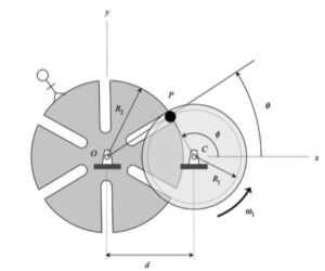
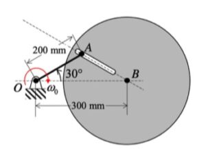
In this problem, we desire to relate the rotation rates of link AB and link OC. With the two rigid bodies connected by a pin-in-slot joint, we are not able to use the rigid body kinematics equations by themselves. Let's discuss that below.

Velocity analysis
Here, we can use the rigid body velocity equation to relate the motions of A and B:

vA = vB + ωAB x rA/B

However, we cannot use a rigid body velocity equation to relate the motion of points O and A (the reason for this is that O and A are not connected by a rigid body). In its place, we can use the moving reference frame velocity equation with an observer attached to link OC:

vA = vO + (vA/O)rel + ω x rA/O

where ω is the angular velocity of the observer, and (vA/O)rel  is the velocity of A as seen by our observer on link OC. Note that with the observer being attached to link OC, this observer sees motion of A only along the slot.

Combine these two equations to produce two scalar equations.

Acceleration analysis
We will use the same procedure for acceleration as we did for velocity - use a rigid body equation for AB and a moving reference frame equation relating O and A.

aA = aB + αAB x rA/B + ωAB x (ωAB x rA/B)
aA = aO + (aA/O)rel + α x rA/O + 2ω x (vA/O)rel + ω x (ω x rA/O)

where α is the angular acceleration of the observer, and (aA/O)rel  is the acceleration of A as seen by our observer on link OC. Again, note that with the observer being attached to link OC, this observer sees motion of A only along the slot.

Combine these two equations to produce two scalar equations.

Homework H3.D - Sp 25

Problem statement
Solution video


DISCUSSION THREAD

Ask and answer questions here through Comments.


DISCUSSION and HINTS
In this problem, we desire to relate the rotation rates of the slotted wheel and the disk. With the two rigid bodies connected by a pin-in-slot joint, we are not able to use the rigid body kinematics equations by themselves. Let's discuss that below.


Before we do, however, can you think of a good application for such a mechanism design? Take a look at this short video.

Velocity analysis
Here, we can use the rigid body velocity equation to relate the motions of P and C:

vP = vC + ωdisk x rP/C

However, we cannot use a rigid body velocity equation to relate the motion of points O and P (the reason for this is that O and P are not connected by a rigid body). In its place, we can use the moving reference frame velocity equation with an observer attached to the slotted wheel:

vP = vO + (vP/O)rel + ω x rP/O

where ω is the angular velocity of the observer, and (vP/O)rel  is the velocity of P as seen by our observer on the disk. Note that with the observer being attached to the slotted wheel, this observer sees motion of P only along the slot.

Combine these two equations to produce two scalar equations.

Acceleration analysis
We will use the same procedure for acceleration as we did for velocity - use a rigid body equation for the disk and a moving reference frame equation relating O and P:

aP = aC + αdisk x rP/C + ωdisk x (ωdisk x rP/C)
aP = aO + (aP/O)rel + α x rP/O + 2ω x (vP/O)rel + ω x (ω x rP/O)

where α is the angular acceleration of the observer, and (aP/O)rel  is the acceleration of P as seen by our observer on the slotted wheel. Again, note that with the observer being attached to the slotted wheel, this observer sees motion of P only along the slot.

Combine these two equations to produce two scalar equations.

Homework H3.A - Sp 25

Problem statement
Solution video


DISCUSSION THREAD

Ask and answer questions here. You learn from both.


DISCUSSION and HINTS
As can be seen from the animation below, the path taken by P is a bit complex. However, what if we put an observer on the non-extending section of the rotating arm - what motion would the observer see for P? Think about that.

Suppose that we do put an observer on the non-extending portion of the rotating arm. That observer would describe the motion of P as being on a straight path aligned with the x-axis. Specifically, we have:

(vP/O)rel = L_dot i
(aP/O)rel = L_ddot i

Using this observer, we can write down the velocity and acceleration of P using the moving reference frame velocity and acceleration equations:

vP = vO + (vP/O)rel + ω x rP/O
aP = aO + (aP/O)rel + α x rP/O + 2ω x (vP/O)rel + ω x (ω x rP/O)

where ω and α are the angular velocity and angular acceleration, respectively, of the observer.

Homework H3.B - Sp 25

Problem statement
Solution video

DISCUSSION THREAD

Ask and answer questions here. Either way, you will learn.


DISCUSSION and HINTS
In this problem, we desire to relate the rotation rates of link OA and the disk.

With the two rigid bodies connected by a pin-in-slot joint, we are not able to use the previous rigid body kinematics equations by themselves. Let's discuss that below.

Velocity analysis
Here, we can use the rigid body velocity equation to relate the motions of O and A:

vA = vO + ωOA x rA/O

However, we cannot use a rigid body velocity equation to relate the motion of points A and B (the reason for this is that A and B are not connected by a rigid body). In its place, we can use the moving reference frame velocity equation with an observer attached to the disk:

vA = vB + (vA/B)rel + ω x rA/B

where ω is the angular velocity of the observer, and (vA/B)rel  is the velocity of A as seen by our observer on the disk. Note that with the observer being attached to the disk, this observer sees motion of A only along the slot.

Combine these two equations to produce two scalar equations.

Acceleration analysis
We will use the same procedure for acceleration as we did for velocity - use a rigid body equation for OA and a moving reference frame equation relating A and B.

aA = aO + αAOx rA/O + ωAO x (ωAO x rA/O)
aA = aB + (aA/B)rel + α x rA/B + 2ω x (vA/B)rel + ω x (ω x rA/B)

where α is the angular acceleration of the observer, and (aA/B)rel  is the acceleration of A as seen by our observer on the disk. Again, note that with the observer being attached to the disk, this observer sees motion of A only along the slot.

Combine these two equations to produce two scalar equations.

Homework H2.I - Sp 25

Problem statement
Solution video


DISCUSSION THREAD

Ask and answer questions here through Comments. You can help others with thoughtful responses to their questions. And, you can learn from the process of doing so.


DISCUSSION and HINTS
This mechanism is made up of three links: AB, BC and the wheel. You are given the constant rotation rate of link AB, and are asked to find the angular velocities and angular accelerations of link BC and of the wheel.

Velocity analysis
Where is the instant center of link BC? What does this location say about the angular velocity of BC?

Acceleration analysis
Write a rigid body acceleration equation for each of the three links in the mechanism:

aB = aA + αAB x rB/A - ωAB2rB/A
aC = aD + αwheel x rC/D - ωwheel2rC/D
aB = aC + αBC x rB/C - ωBC2rB/C

where D is the point on the wheel in contact with the ground. Note that the horizontal component of aD is zero, whereas the vertical component of aD is not zero. Combining together these three vector equations in a single vector equation will produce two scalar equations in terms of αwheel and αBC .

Homework H2.J - Sp 25

Problem statement
Solution video


DISCUSSION THREAD

Ask and answer questions here. Help others with thoughtful responses to their questions. You will learn from the experience.


DISCUSSION and HINTS
This mechanism is made up of three links: AB, BD and DE. You are given the rotation rate of link AB, and are asked to find the angular velocities and angular accelerations of links BD and DE. At the position shown, it is known that ωAB = constant.

From the animation below, we are reminded that B and D move on circular arc paths with centers at A and E, respectively. The velocities of B and D are always perpendicular to the lines connecting the points back to the centers of the paths. Can you visualize the location of the instant center (IC) of link BD as you watch this animation? For the position of interest in this problem, you see in the animation that the velocities for all points on BD are the same - is this consistent with the location of the IC for BD at that position?

Velocity analysis
Where is the instant center of link BD? What does this location say about the angular velocity of BD?

Acceleration analysis
Write a rigid body acceleration equation for each of the three links in the mechanism:

aB = aA + αAB x rB/A - ωAB2rB/A
aD = aE + αDE x rD/E - ωDE2rD/E
aB = aD + αBD x rB/D - ωBD2rB/D

Combining together these three vector equations in a single vector equation will produce two scalar equations in terms of αBD and αDE.

Homework H2.G - Sp 25

Problem statement
Solution video


DISCUSSION THREAD

Ask and answer questions here. Helping a colleague with their questions is often as educational as is asking questions yourself.


DISCUSSION and HINTS

As discussed in lecture, we can locate the instant center (IC) for a rigid body through knowledge of the direction of motion for two points on that body. Here, we want to know the location of the IC for link BD. To this end:

  • The path of B is circular with its center at A. Therefore, the velocity of B vB is vertical.
  • The path of D is circular with its center at E. Therefore, the velocity of D vD is horizontal.
  • Draw a line that is perpendicular to vB , and draw a line that is perpendicular to vD. The intersection of these two perpendiculars is the IC for link BD. See the animation below that shows how the location of the IC for for BD moves as the mechanism moves. It is called the "instant" center because its location changes from instant to instant.

Recall, also, that the speed of any point on a rigid body is equal to the angular speed of the body times the distance from that point to the IC for that body. This provides you with the equations needed to find the angular velocities of links BD and DE.

Homework H2.E - Sp 25

Problem statement
Solution video


DISCUSSION THREAD

Ask and answer questions here. Give your colleagues some help with thoughtful responses. You can learn for that experience.


DISCUSSION

As you watch the animation below, you see that C moves back and forth along a straight path. In general, C has a non-constant speed; therefore, with the path of C being straight, its acceleration is always directed along the path of C. Point B, on the other hand, moves along a circular arc path with a non-constant speed. Owing to the curvature of the path of B, the general acceleration of B is directed neither purely tangent nor purely normal to the path of B. Using our earlier understanding of the path description of motion, the normal component of acceleration of B is due to the centripetal term of vB2/r. Note in the animation that for positions of B for which vB = 0, the acceleration of B is tangent to the path.


HINTS
Velocity analysis
As recommended in lecture, we should write down a rigid body velocity equation for each rotating link in the mechanism. For this problem, we should use:

vB = vA + ωAB x rB/A
vB = vC + ωBC x rB/C

For these two equations, we know both vA(= 0) and vC . Equating these two equations gives two scalar equations in terms of ωAB and ωBC .

Acceleration analysis
Similarly for acceleration, we should use:

aB = aA + αAB x rB/A - ωAB2rB/A
aB = aC + αBC x rB/C - ωBC2rB/C

For these two equations, we know both aA(= 0) and aC . Equating these two equations gives two scalar equations in terms of αAB and αBC .

Homework H2.F - Sp 25

Problem statement
Solution video


DISCUSSION THREAD

Ask your questions here. And, consider answering questions of your colleagues here. Either way, you can learn.


DISCUSSION THREAD

At first read through, the motion of the disk rolling on the translating wedge looks complicated. It turns out not be be so complicated; rather, it can be described through a straight-forward expression of the rigid body kinematics equation for the disk. If we focus our attention on the disk by itself, we know the direction of of motion for two points on the disk: point O moving in the negative y-direction with an unknown speed of vO, and since point C does not slip on the wedge, C moves in the negative x-direction with a known speed of vC = vA. This is as shown in the following figure.

From this, we can write the following vector kinematics equation for the disk:
vC = vO + ω x rC/O

Although this is a single vector equation, it is made up of two scalar equations due to its x- and y-components. These two scalar equations are in terms of two unknowns: ω and vO. For Part (a), solve these two equations.

For Part (b), you can now write the rigid body kinematics equations relating points O and B in order to find the vector velocity expression for point B:
vB = vO + ω x rB/O.