| Problem statement Solution video |
DISCUSSION THREAD

Ask and answer questions here through Comments. You can help others with thoughtful responses to their questions. And, you can learn from the process of doing so.
DISCUSSION and HINTS
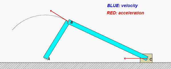
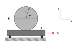
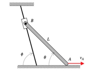
This mechanism is made up of three links: AB, BC and the wheel. You are given the constant rotation rate of link AB, and are asked to find the angular velocities and angular accelerations of link BC and of the wheel.
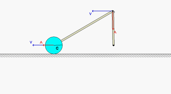
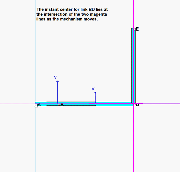
Velocity analysis
Where is the instant center of link BC? What does this location say about the angular velocity of BC?

Acceleration analysis
Write a rigid body acceleration equation for each of the three links in the mechanism:
aB = aA + αAB x rB/A - ωAB2rB/A
aC = aD + αwheel x rC/D - ωwheel2rC/D
aB = aC + αBC x rB/C - ωBC2rB/C
where D is the point on the wheel in contact with the ground. Note that the horizontal component of aD is zero, whereas the vertical component of aD is not zero. Combining together these three vector equations in a single vector equation will produce two scalar equations in terms of αwheel and αBC .