Category Archives: Chapter 3 Homework

Homework H3.I - Sp 25

Problem statement
Solution video

DISCUSSION THREAD

Any questions??


Discussion and hints:

You need to write down the angular velocity and angular acceleration of the football. Based on what we have been doing up to this point in Chapter 3, hopefully it is clear that the football (and insect) has two components of angular velocity: ω1 about the fixed X-axis and ω2 about the moving x-axis. Take a time derivative of the angular velocity vector to find the angular acceleration of the football (observer).


Homework H3.G - Sp 25

Problem statement
Solution video


DISCUSSION THREAD

Ask and answer questions here. And, learn from both.


DISCUSSION and HINTS

For your work on this problem, it is recommended that you use an observer attached to the disk. The observer/disk has two components of rotation:

  • One component of ω0 about the fixed K-axis.
  • The second component of ωdisk about the moving j-axis.

Write out the angular velocity vector ω in terms of the two components described above.

Take a time derivative of ω to get the angular acceleration α of the observer/disk. When taking this derivative, you will need to find the time derivative of the unit vector j. How do you do this? Read back over Section 3.2 of the lecture book. There you will see: j_dot = ω x j, where ω is the total angular velocity vector of the disk that you found above.

Acceleration of point A
The motion of A is quite complicated. To better understand the motion of A, consider first the view of point A by our observer who is attached to the disk - what does this observer see in terms of relative velocity and relative acceleration: (vA/B)rel and (aA/B)rel?

With this known relative motion, we can use the moving reference frame acceleration equation:

aA = aB + (aA/B)rel +α x rA/B + 2 ω x (vA/B)rel + ω x (ω x rA/B)

In finding the acceleration of B, aB, note that B moves with a constant speed on a circular path centered on point O. Use the path description to find aB. WARNING: Although B moves with a constant speed, its acceleration is NOT zero.

Homework H3.H - Sp 25

Problem statement
Solution video


DISCUSSION THREAD

Ask and answer questions here. And, learn from both.

CHANGE IN PROBLEM STATEMENT:  Please use θ = 0 = constant when solving this problem.


DISCUSSION and HINTS

For your work on this problem, it is recommended that you use an observer attached to the disk. The observer/disk has two components of rotation:

  • One component of ω0 about the fixed J-axis.
  • The second component of ω1 about the moving i-axis.

Write out the angular velocity vector ω in terms of the two components described above.

Take a time derivative of ω to get the angular acceleration α of the observer/disk. When taking this derivative, you will need to find the time derivative of the unit vector i. How do you do this? Read back over Section 3.2 of the lecture book. There you will see: i_dot = ω x i, where ω is the total angular velocity vector of the disk that you found above.

Velocty of point A
The motion of A is quite complicated. To better understand the motion of A, consider first the view of point A by our observer who is attached to the disk - what does this observer see in terms of relative velocity: (vA/O)rel?

With this known relative motion, we can use the moving reference frame velocity equation:

vA = vO + (vA/O)rel + ω x rA/O

Homework H3.E - Sp 25

Problem statement
Solution video


DISCUSSION THREAD

Ask your questions here. You can also answer questions of others. You can learn from helping others.


DISCUSSION and HINTS

Bar OA has two components of rotation:

  • One component of Ω about the fixed J-axis.
  • The second component of θ_dot about the moving k-axis.

Write out the angular velocity vector ω in terms of the two components described above.

Take a time derivative of ω to get the angular acceleration α of the bar. When taking this derivative, you will need to find the time derivative of the unit vector k. How do you do this? Read back over Section 3.2 of the lecture book. There you will see: k_dot = ω x k, where ω is the total angular velocity vector of bar OA that you found above.

Homework H3.C - Sp 25

Problem statement
Solution video


DISCUSSION THREAD

Ask and answer questions here through Comments.


DISCUSSION and HINTS
In this problem, we desire to relate the rotation rates of link AB and link OC. With the two rigid bodies connected by a pin-in-slot joint, we are not able to use the rigid body kinematics equations by themselves. Let's discuss that below.

Velocity analysis
Here, we can use the rigid body velocity equation to relate the motions of A and B:

vA = vB + ωAB x rA/B

However, we cannot use a rigid body velocity equation to relate the motion of points O and A (the reason for this is that O and A are not connected by a rigid body). In its place, we can use the moving reference frame velocity equation with an observer attached to link OC:

vA = vO + (vA/O)rel + ω x rA/O

where ω is the angular velocity of the observer, and (vA/O)rel  is the velocity of A as seen by our observer on link OC. Note that with the observer being attached to link OC, this observer sees motion of A only along the slot.

Combine these two equations to produce two scalar equations.

Acceleration analysis
We will use the same procedure for acceleration as we did for velocity - use a rigid body equation for AB and a moving reference frame equation relating O and A.

aA = aB + αAB x rA/B + ωAB x (ωAB x rA/B)
aA = aO + (aA/O)rel + α x rA/O + 2ω x (vA/O)rel + ω x (ω x rA/O)

where α is the angular acceleration of the observer, and (aA/O)rel  is the acceleration of A as seen by our observer on link OC. Again, note that with the observer being attached to link OC, this observer sees motion of A only along the slot.

Combine these two equations to produce two scalar equations.

Homework H3.D - Sp 25

Problem statement
Solution video


DISCUSSION THREAD

Ask and answer questions here through Comments.


DISCUSSION and HINTS
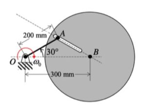
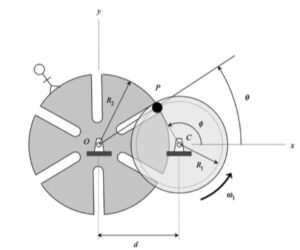
In this problem, we desire to relate the rotation rates of the slotted wheel and the disk. With the two rigid bodies connected by a pin-in-slot joint, we are not able to use the rigid body kinematics equations by themselves. Let's discuss that below.


Before we do, however, can you think of a good application for such a mechanism design? Take a look at this short video.

Velocity analysis
Here, we can use the rigid body velocity equation to relate the motions of P and C:

vP = vC + ωdisk x rP/C

However, we cannot use a rigid body velocity equation to relate the motion of points O and P (the reason for this is that O and P are not connected by a rigid body). In its place, we can use the moving reference frame velocity equation with an observer attached to the slotted wheel:

vP = vO + (vP/O)rel + ω x rP/O

where ω is the angular velocity of the observer, and (vP/O)rel  is the velocity of P as seen by our observer on the disk. Note that with the observer being attached to the slotted wheel, this observer sees motion of P only along the slot.

Combine these two equations to produce two scalar equations.

Acceleration analysis
We will use the same procedure for acceleration as we did for velocity - use a rigid body equation for the disk and a moving reference frame equation relating O and P:

aP = aC + αdisk x rP/C + ωdisk x (ωdisk x rP/C)
aP = aO + (aP/O)rel + α x rP/O + 2ω x (vP/O)rel + ω x (ω x rP/O)

where α is the angular acceleration of the observer, and (aP/O)rel  is the acceleration of P as seen by our observer on the slotted wheel. Again, note that with the observer being attached to the slotted wheel, this observer sees motion of P only along the slot.

Combine these two equations to produce two scalar equations.

Homework H3.A - Sp 25

Problem statement
Solution video


DISCUSSION THREAD

Ask and answer questions here. You learn from both.


DISCUSSION and HINTS
As can be seen from the animation below, the path taken by P is a bit complex. However, what if we put an observer on the non-extending section of the rotating arm - what motion would the observer see for P? Think about that.

Suppose that we do put an observer on the non-extending portion of the rotating arm. That observer would describe the motion of P as being on a straight path aligned with the x-axis. Specifically, we have:

(vP/O)rel = L_dot i
(aP/O)rel = L_ddot i

Using this observer, we can write down the velocity and acceleration of P using the moving reference frame velocity and acceleration equations:

vP = vO + (vP/O)rel + ω x rP/O
aP = aO + (aP/O)rel + α x rP/O + 2ω x (vP/O)rel + ω x (ω x rP/O)

where ω and α are the angular velocity and angular acceleration, respectively, of the observer.

Homework H3.B - Sp 25

Problem statement
Solution video

DISCUSSION THREAD

Ask and answer questions here. Either way, you will learn.


DISCUSSION and HINTS
In this problem, we desire to relate the rotation rates of link OA and the disk.

With the two rigid bodies connected by a pin-in-slot joint, we are not able to use the previous rigid body kinematics equations by themselves. Let's discuss that below.

Velocity analysis
Here, we can use the rigid body velocity equation to relate the motions of O and A:

vA = vO + ωOA x rA/O

However, we cannot use a rigid body velocity equation to relate the motion of points A and B (the reason for this is that A and B are not connected by a rigid body). In its place, we can use the moving reference frame velocity equation with an observer attached to the disk:

vA = vB + (vA/B)rel + ω x rA/B

where ω is the angular velocity of the observer, and (vA/B)rel  is the velocity of A as seen by our observer on the disk. Note that with the observer being attached to the disk, this observer sees motion of A only along the slot.

Combine these two equations to produce two scalar equations.

Acceleration analysis
We will use the same procedure for acceleration as we did for velocity - use a rigid body equation for OA and a moving reference frame equation relating A and B.

aA = aO + αAOx rA/O + ωAO x (ωAO x rA/O)
aA = aB + (aA/B)rel + α x rA/B + 2ω x (vA/B)rel + ω x (ω x rA/B)

where α is the angular acceleration of the observer, and (aA/B)rel  is the acceleration of A as seen by our observer on the disk. Again, note that with the observer being attached to the disk, this observer sees motion of A only along the slot.

Combine these two equations to produce two scalar equations.