| Problem statement Solution video |
DISCUSSION THREAD
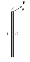
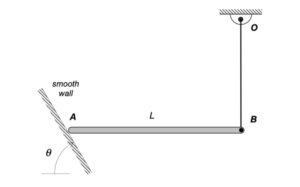
NOTE: The view of the figure provided is that of the rod as seen from above the surface on which the rod lies. Gravity is directed into the screen.
DISCUSSION
This is a straight-forward application of the Newton-Euler equations to a single rigid body moving in a plane. Consider the four-step plan:
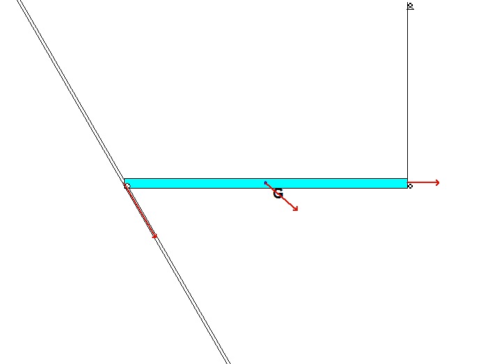
1. FBD: Only a single force acting on the body in its plane of motion.
2. Newton/Euler: Use the two components of the Newton equations and one Euler equation for the rigid body:
∑Fx = … = m*aGx
∑Fy = … = m*aGy
∑MG = … = IG*α
3. Kinematics: None needed here.
4. Solve
Any questions?? Please ask/answer questions regarding this homework problem through the “Leave a Comment” link above.