Category Archives: Chapter 6 Homework

Homework H6.C - Sp24

Problem statement
Solution video

https://youtu.be/x2WbSYYYSAI


DISCUSSION THREAD

Ask your questions here. Or, answer questions of others here. Either way, you can learn.


DISCUSSION and HINTS
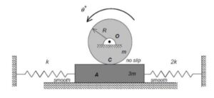
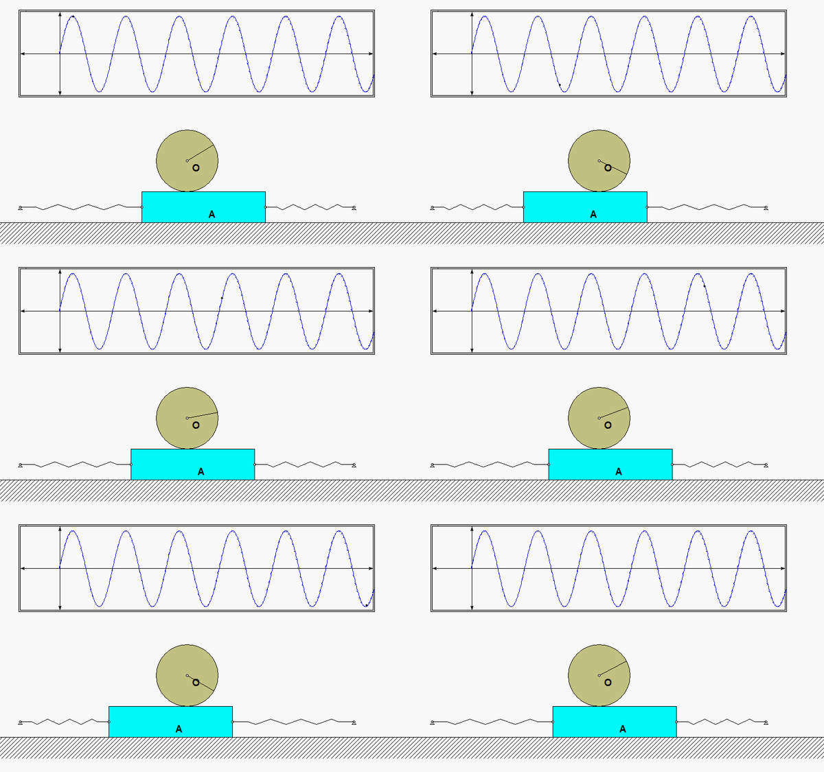
As the system moves, there is no slipping between the contact point C on the drum and block A.  This represents a constraint between the drum rotation and the block translation. We will deal with this in Step 3 of the derivation of the equation of motion below.
Recall the following four-step plan outline in the lecture book and discussed in lecture:

Step 1: FBDs
Draw individual free body diagrams (FBDs) of the drum and the disk. Be sure to include the equal-and-opposite contact forces on both the drum and the block. It is important to temporarily define a coordinate that describes the motion of the block. Let's call that variable "x", and define it to be positive to the right. With this definition, the spring forces on the left and right side of the block are kx and 2kx, respectively, with both forces pointing to the left.

Step 2: Kinetics (Newton/Euler)
Using your FBDs from above, write down the Euler equation for the drum, and the Newton equation for the block. Combine these two equations through the elimination of the drum-to-block contact force.

Step 3: Kinematics
You need to relate the angular acceleration of the drum to the acceleration of the block. How is this done? What are the results? Also, how do you relate the stretch/compression x in the two springs in terms of θ?

Step 4: EOM
From your equations in Steps 2 and 3, derive the equation of motion (EOM) of the system in terms of θ.

Once you have determined the EOM for the system, identify the natural frequency from the EOM. Also from the EOM, we know that the general form of the response is: θ(t) = C*cos(ωnt)+ S*sin(ωnt). How do you find the response coefficients C and S?
Homework H6.D - Sp24

Problem statement
Solution video

https://youtu.be/wBj4GVVNZgg


DISCUSSION THREAD

Discussion and hints:

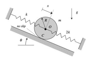
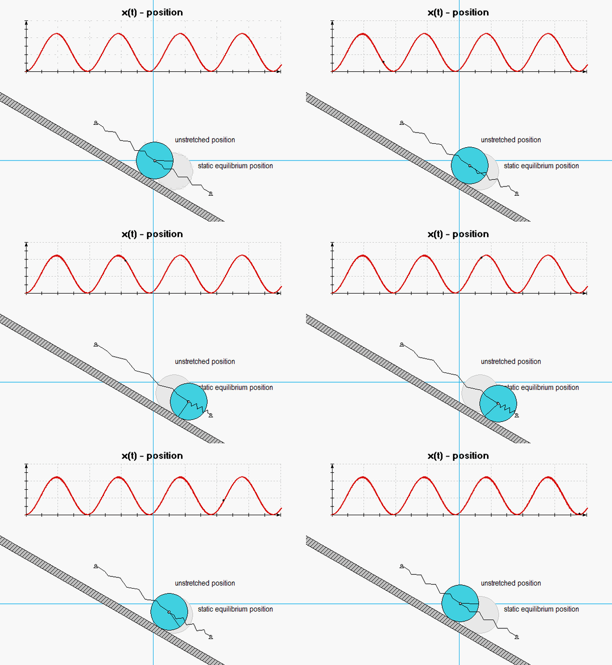
The derivation of the dynamical equation of motion (EOM) for a system is a straight-forward application of what we have learned from Chapter 5 in using the Newton-Euler equations. The goal in deriving the EOM is to end up with a single differential equation in terms of a single dependent variable that describes the motion of the system. Here in this problem, we want our EOM to be in terms of x(t).

Recall the following four-step plan outline in the lecture book and discussed in lecture:

Step 1: FBDs
Draw a FBD of the disk. Define a rotation coordinate for the disk.

Step 2: Kinetics (Newton/Euler)
Write down the Newton/Euler equations for the disk.

Step 3: Kinematics
Use the no-slip condition between the disk and the ramp to relate x to the rotational coordinate that you chose above.

Step 4: EOM
Combine your Newton/Euler equations along with your kinematics to arrive at a single differential equation in terms of the dependent variable x.


Any questions?

Homework H6.A - Sp24

Problem statement
Solution videohttps://www.youtube.com/watch?v=8-WefHE4bMc

NOTE: Please complete ONLY Part (a). Do not work on Part (b).


DISCUSSION THREAD

Any questions?? Please ask/answer questions regarding this homework problem through the "Leave a Comment" link.


Discussion and hints

The four-step plan:

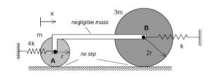
  1. FBD: It is recommended that you draw individual free body diagrams of each disk and of bar AB. Note that the mass of AB is negligible and that forces are applied at only two points (i.e., a two-force member). What does this say about the direction of the forces on the disks at A and B?
  2. Kinetics: Recommended that you use an Euler equation about the contact point of each disk since those are no-slip points for whose accelerations are directed toward the center of mass of each disk. Note that both of these two equations will involve the load carried by AB. You can eliminate that load from these equations, resulting in a single equation.
  3. Kinematics: Note that rigid bar AB insures that the velocities of points A and B are the same. How can this be used to relate the angular accelerations of the two disks? Can you see this kinematic relationship between the angular accelerations in the animation above? Please note that the angular accelerations of the two disks are NOT the same, although their centers have the same accelerations.
  4. EOM: Combine your results from Steps 2 and 3 to produce a single differential equation of motion (EOM) in terms of the x-coordinate.