Problem statements
Solution video – H24.A
Solution video – H24.B
DISCUSSION THREAD

Please post questions here on the homework, and take time to answer questions posted by others. You can learn both ways.
Problem statements
Solution video – H24.A
Solution video – H24.B
DISCUSSION THREAD

Comments are closed.
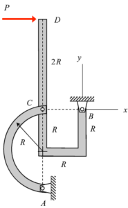
Are there only two-sets of forces on the curved bracket system AC (Cx,Cy and Ax,Ay)? I feel like I’m missing something because the moment about A when just looking at the curved bracket is gives that the X-forces equal zero, but for some reason this doesn’t feel right. Did I miss a force?
I also set up the problem this way and found that the X-forces equal zero. I do not think you are missing anything when setting up this problem.
I too have a similar question regarding this problem. I think that having the x direction reaction forces being zero makes some sense on that bracket system, as the force P is handled by the force Bx.
You’d be right to think so. Because after having the x direction reaction forces be zero makes sense and I even did a little bit of the math to make sure that they are actually zero. So I think we’re all on the right track.
I also got zero for the sum of the x forces, I think what you did was correct
No I do not think you missed any forces. I think there are only those two sets of forces.
When drawing the two mechanisms, it was important to make sure that the C reaction forces were in opposite directions for each FBD. That is to say Cx pointing to the right in one diagram would be Cx pointing to the left in another. This is important as it determines your signs for the equilibrium equations.
Could you treat the semi-circle bar as a two force member since no other external forces are applied on it but the reaction forces?
I believe you can. It has only the two sets of forces at the two joints for it. The pin joint and where it connects to the U shaped bar at C. When doing the FBD and calculations for the U shaped bar, I suppose you can treat it as a two force member to simplify the system. The forces will act in one line through the two points. And as people said the X forces equal zero so the idea stands.
I’m not sure if this would be helpful, however, because we need to write the reactions at A in vector form regardless, so we need to break them down into x and y components at the end anyway.
After looking at the figure, I think that the best way to solve this problem is by separating the two figures and perhaps calculating the moment of C for each. This could help isolate all the variables, especially when looking at the BD figure, for when you take the moment about C there you can instantly solve for By.
You can simplify the work being done if you identify member AC to be a two force member. This means that the forces will only be working along its axis reducing the number of forces you need to consider.
Using Newton’s Third law to break up the system is very useful in this problem and helps save time significantly. I used the full body diagram of the whole system. I then broke the system into two subparts. The first one is the half circle segment, and you can use static equilibrium equations on that subgroup to quickly solve for one of the reaction forces at C by relating them to A. The other subsystem I used was the entire hook-shaped segment without the half circle attached. Use newton’s third law to account for the solved and unsolved forces at C from the half circle segment and place a moment equation where you can ignore the reaction forces at B to solve for the remaining force at C. Now you know both reaction forces at A from static equilibrium equations on the half circle segment to relate Cx and Cy to Ax and Ay and you have enough forces on the hooked subgroup to solve for B’s reaction forces with static equilibrium equations.
For this problem and other types that are similar to these, I found it helpful to keep track of what you are trying to solve and keeping those forces positive if possible. Then making the other forces that related to Newton’s Third Law negative, since they may not even be used to find your final answer.
For the non-curved member, are the reactions at point B Bx and By? I’m confused on how to take the moment at C if there were two reaction forces as there would be two unknowns in the moment equation.
If you draw individual FBDs for the two components, you can get two variants for the semi-circle member. One of them will be a 2-force member, which does not necessarily have to be a truss member. Using either of the two FBD variants should result in the correct same answer
Do the members apply forces or moments on each other?