Problem statements
Solution video – H28.A
Solution video – H28.B
DISCUSSION THREAD
Please post questions here on the homework, and take time to answer questions posted by others. You can learn both ways.
Problem statements
Solution video – H28.A
Solution video – H28.B
DISCUSSION THREAD
Comments are closed.
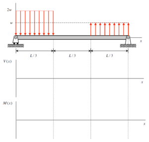
Hey! I’m working on this beam problem (H28.B) for class, and I’m stuck on the shear force and bending moment diagrams. The beam has a varying load (2w, w, 2w), and I’m not sure how to break it down. Anyone have tips on how to handle the reactions and get the diagrams right?
I found the Shear Force/Bending Moment Diags – Dist. Load Example 2 video to be very useful as I was doing this question. I split up the beam into 3 sections. First start with your overall FBD to solve for reaction forces at the two ends. Then solve for each section. Make sure to keep the distributed load in terms of x for the section you are solving for. Also, the middle section has no distributed load. When graphing, the middle section should end up being linear for moment and constant for shear.
What would happen if the distributed was not uniform, and had either a linear or exponential relationship?
For a linear relationship, you could probably break it down into shapes with known distributions. For exponential, you will most likely use integrals.
Similar to when we were finding centroids, we could break it down into composite parts or use integrals based on the shape. In the question asked if there are curves that are not circles or ellipses, then a definite integral is probably the only way to break the distributions down. Otherwise, I’m sure we can utilize similar techniques like the composite parts for centroids.
For this problem I split the beam into 3 segments to solve for the moment and shear equations. Is this the approach others took to solving this problem?
Yeah that’s the approach you should take when solving problems with point loads instead of distributive loads.
Yeah splitting them and finding the force for each is the correct way to go.
Hey, yes that is the aproach I used as well in the end by taking the loads as point loads. Makes it much easier (and is the only way I found to solve this problem).
In the middle section, since we are completely past the distributed force, can we treat that as a force equivalent at a point? That way the shear force becomes a fixed value on that interval and the only thing changing is the bending moment?
I believe so – I treated the force as a point 1 ft from the left edge. I then got a constant shear force and linear moment equation.
Are we allowed to take the integral of shear force to find our bending moment or are we supposed to find bending moment separately through static equilibrium?
Based on the first example problem that the professor worked through last class (rework of 9.A.2), I think that finding the bending moment through integration is the intended way to find the solution in this problem. I also found it useful to reference the procedure on page 356 of the textbook when setting up my integrals.
I agree that the problem can be solved by doing the integral of P(x) and then V(x). However, it can also be solved by splitting the problem into 3 sections of L/3, drawing the FBDs, and solving for V and M in static equilibrium. The relationship between the equations for P(x), V(x), and M(x) can then be used to check your work.
I took the integral and it worked just fine, I’d say whichever is easier because both should give the same answer.
Since the beam is only loaded at 2 points, when we divide the beam up into various segments, do we also consider the middle part where there is no load as a segment to solve for the moment and shear force?
The shear force should have no change and will stay at the same value from L/3 to 2L/3, which means the change in the moment from those points will be constant.
Does the moment graph tell us about the stress on the object? If the graph shows a mostly positive moment or mostly negative moment does it say anything about the impending bend of the object?
Something that was useful to me when solving this problem was the fact that linear loads could always be written in terms of X. Because I used a method where I progressively extended the FBD of the beam rather than dividing it into three pieces, representing the line loads in terms of X helped ensure the Shear Force equation made sense for variable points on the beam.
I agree, splitting it up in terms of x can really help a lot. I personally split it up into three equal pieces here, and not use “x” to split them up. However, I can see how using “x” can be more intuitive and easier to set up the problem.
When making the moment graph, does the line make a exponential curve as the distance and force both increase? If so, do we need to properly draw the curve or will an estimate work?
Yes, the moment diagram forms a parabolic curve under a uniformly distributed load. A well-estimated curve with correct key points is probably acceptable for the diagrams.
I am unsure what is the best way to break up this segment with the gap between the next force. Is it best to do the first 2/3 together or the second 2/3s together?
I found the second example for the distributed loads (on brightspace) to be helpful in having an approach for this. I found really difficult to deal with the third segment but then I realized that I have to be very careful with my distances, moments, and the load on the last section. I tried to use M’ = V to verify my solutions though.
For this problem, it is necessary to begin by determining the reaction forces at the ends of the beam. After these forces are determined, they should be plotted on the V(x) graph. The leftmost force should be as is, while the rightmost force should be its inverse (this is because the shear will be zero after the reaction force is applied at this point). Since there are distributed loads, these apply a constant shear force (a straight line). To determine the moment graph, take the integral of the shear graph (remember that critical points on the shear are extrema on the moment). Use area under the triangle to determine the max/min moments.