Chapter 12 – Landscape Drawings & Specifications – Indiana Accredited Horticulturist Program

Chapter 12 – Landscape Drawings & Specifications

Learning Objectives

From reading and studying this chapter, you should be able to:
  • Understand how drawings and specifications communicate landscape design information from a design team to the implementation team.
  • Know the contents and structure of specification sets and drawing
  • Read and understand landscape
  • Read and understand a layout plan, a grading plan and a planting

Introductory Comments

This chapter is intended to familiarize the student with the formal documents that are required to communicate ideas among all the various persons involved in developing a landscape. Not all workers at all levels of a project will come in contact with all of these documents. However, the more one knows the “big picture” the easier it is to see how one’s work fits into the whole.

Contract Documents

Before a landscape development project is constructed, an agreement is struck between the owner of the project (often called the developer) and the landscape installer (often called the landscape contractor). That agreement spells out exactly what the developer wants the landscape contractor to do. That agreement is a contract. In order for the contract to spell out “exactly what the developer wants the landscape contractor to do” it must contain specific and detailed information. Although an oral agreement may suffice in extremely simple projects, in most cases drawings and written text (usually called plans and specifications) provide the means of conveying design and construction information. Because the plans and specifications make up the complete basis for the contract between the developer and the landscape contractor, they are commonly referred to as contract documents. Contract documents include a great deal of information needed to complete the project. Included, for example, is information on materials and construction techniques, the form of intended walls, beds, walks, and plantings, the legal rights of each party in disputes, the compensation for work completed, required schedules, etc. Every detail in the contract documents is important. Once entered into, the contract is legally binding on the signers.  Horticulturists are primarily concerned with the plans that relate to the installation of plants and with the accompanying technical planting specifications. Contract document sets for landscape development generally follow a common format. The details of what is included vary with each project and whether it is public or private work. Table 1 presents a list of typical text documents commonly included in contract document sets for public projects. These are generally referred to as Specifications.  Often in private work, several are omitted. Most of the text documents listed are legalistic in nature or pertain to the business and management of the project. For persons directly involved in horticultural aspects of the work, the Technical Specifications (and documents that may alter them, i.e. Addenda and Change Orders) are of the most importance. Typical Drawings or illustration documents are listed in Table 2 These plans vary directly with the nature of the project. For example, if there is no intent to make landform changes in the project, there is no need for a grading plan. If simple landform changes are planned, the grading plan may be sufficient to tell the story without the need for illustrative sections or elevation drawings. Several drawings or plans are of importance to the horticultural professional including the demolition, layout and grading plans. However, much construction is beyond the scope of what landscape contractors generally do. Of greatest direct interest is the planting plan.
Table 1. Typical Written Text Documents Included in Contract Document Sets (Specifications)
Document Explanation
Title page project name, owner, date
Invitation to Bid an advertisement usually published in local newspapers and area trade journals to alert potential bidders to the availability of the project and to invite them to submit a bid
Index to Specifications same as a Table of Contents for the text documents
List of Drawings same as a Table of Contents for the plans
Instructions to Bidders detailed information for the preparation & submission of bids
Affidavits (various) These are sworn statements by the contractor. It is usually required that the contractor swear that there has been no collusion (price fixing) during the preparation of the bid. Other sworn statements may be required that help assure there has been no racial discrimination in hiring, or other activities prohibited by law.
Bid Form official form on which to submit a bid
Form of Contract   the example of how the actual contract will be structured
Performance Bond Form official form on which to submit information pertaining to the bidder’s ability to obtain a performance bond. The successful bidder is usually required to provide a performance bond (a monetary guarantee) that serves as insurance for the owner against the contractor’s failure to complete the work.
Certificate of Insurance  certifies that the contractor has certain insurance coverages
Pre-qualification form form used by a bidder to supply information (work history, equipment, financials, etc.) to help the owner determine whether the bidder is qualified to do the work. For public work in Indiana, Form 96A is used.
Payment Form  form for use by the contractor to request incremental payments from the owner as the work is completed
General Conditions  contains many, many legal details about the rights & responsibilities of the contracting parties
Supplemental Conditions contains more legal details about rights & responsibilities of the contracting parties, particularly as they apply to a specific contract
Schedule of Prevailing Wages      wages that must be paid to workers on this contract. These are wage levels that are set by public agencies under applicable state or federal law (generally applies only to publicly funded work)
Surface and Sub-surface Data  existing site information
Statement of Payment of Taxes   contractor’s indication of payment of all sales taxes, etc.
Bid Security Form form to accompany a bidder’s bid guarantee. The bid guarantee is a specified amount of money that the bidder posts to the owner at the time of bid submission that may be forfeited if the bidder is selected to do the work, but fails to sign a contract for the job.
Technical Specifications specific written details about what and how to construct the project
Addendum (pl. addenda) A document making a change to the contract documents.
Addenda may be issued by the owner during the bid preparation period, but prior to bid opening and contract awarding.
Change Order(s) A document making a change to the contract documents. Change orders may be issued by the owner after the contract is signed and/or the project work has begun.
Table 2. Typical Illustration Documents Included in Contract Document Sets (Drawings).
Document Explanation
Existing Conditions       shows the site as it is before work begins, often including the location of underground utilities
Demolition Plan                      indicates what existing features on the site should be removed and/or destroyed before new work begins
Site Plan                                  shows the overall project. It illustrates how the work occupying the site and it shows any parts of the site that are outside the area of work (outside the work limit line).
Layout Plan                      shows precise sizes, shapes and measurements of all the structural elements in the finished project
Grading Plan  this is a type of topography map that shows the shape and form of the existing and proposed land surface using topographic lines for elevations
Elevations  these may supplement the grading plan and further illustrate the finished shape and form of the land and elements on the land, using the vertical dimension
Planting Plan shows all the plants, their intended locations on the site, and the quantity, size and root condition of all (usually a summary table is located on this plan, called the Plant List)
Details show close-up information of how key elements are to be constructed or how plants are to be planted.
Additional Plans other drawings may, for example, illustrate an irrigation system (piping, fittings, appurtenances, etc.) or landscape lighting (wiring, controllers, fixtures, etc.)

Understanding Technical Specifications

Technical specifications are commonly written in language that is best described as “legalese.” That is, they may read like court documents written by a lawyer. Of course, given that specifications are part of contract documents and the contract is a legally binding agreement, it makes sense that they should be that way. Specifications are best when they are clear and easily understood in spite of their legal sound. Excellent specifications are precise in their use of words and grammar. Misunderstandings about what is intended or required can make projects slower, more expensive and can lead to ill will between owners and con- tractors. Ambiguous language that can be interpreted in more than one way or is confusing has no place in specifications set. Conversely, it is essential that the landscape contractor read the specifications thoroughly and carefully so as to gather a complete understanding of the project and its many details. Correct and current landscape horticultural and construction practices should also be a part of well-written specifications. Antiquated methods that are no longer widely practiced tend to be ignored. That, too can lead to ill will between parties. Information that is contained in specifications should not be restated on drawings. Conversely, if information is given on a drawing, it need not be restated in the technical specifications. Although there is never an intent to confuse, information stated more than one place can cause problems. During the final stages of contract document preparation (often under stress and in haste), changes may be made in one place, but forgotten in the other, leading to contradictory information. In cases where the “same” information is stated one way in the technical specifications and differently on drawings, it is generally held that the specifications govern. Finally, a good specification set is specific to the project for which it is prepared. It should contain only specification sections for types of construction or planting in the project. The inclusion of sections about types of work that are not included in a given project led to confusion over what is, or is not, actually in the job. Overall, construction specifications including landscape construction generally follow a format prescribed by the Construction Specifications Institute (CSI). CSI Division 2 – Sitework includes Section 02800 “Site Improvements” and Section 02900 “Landscaping.” Within these sections, specifications follow this common structure:
  • General information, references and standards
  • Materials to be installed, or Products
  • Methods of installation, or Execution Document 1, on the CD only, presents a complete example of a Section 02900 )
The four basic types of specifications are descriptive, performance, proprietary and reference. Descriptive specifications are most common. They describe in detail what is to be done and exactly how it is to be accomplished (Example 1). Performance specifications define a result, but do not give precise instructions on how to achieve that result. This type is not common in landscape work. Proprietary specifications are those that define a particular product from a particular manufacturer or supplier. They may be either “closed” or “open.” Closed means there is no alternative for the contractor, but to supply exactly the product called for. Open specifications often use terms such as “comparable,” or “equal.” This allows for a similar product to be supplied (not the exact one listed), subject to the approval of the owner or his design representative (Example 2). A Reference specification is one that refers to another authority that sets standards. This avoids the entire standard having to be reproduced in the current specification (Example 3).

Example 1. Example of a descriptive technical specification. This entire section is descriptive of methods to be used in the planting process.


3.05     PLANTING TREES AND SHRUBS

  1. Set balled and burlapped stock plumb and in center of pit or trench with top of ball raised above adjacent finish grades as indicated.
    1. Place stock on setting layer of compacted planting
    2. Remove wire baskets from balls and burlap partially from top and sides, but do not remove burlap from under Remove pallets, if any, before setting. Do not use planting stock if ball is cracked or broken before or during planting operation. Root flare must be exposed at surface or plant shall be rejected. Contractor may carefully shave soil from top of root ball exposing root flare.
    3. Place backfill around ball in layers, tamping to settle backfill and eliminate voids and air When pit is approximately 3/4 backfilled, water thoroughly before placing remainder of backfill. Repeat watering until no more is absorbed. Water again after placing and tamping final layer of backfill.
  2. Set container-grown stock plumb and in center of pit or trench with top of ball raised above adjacent finish grades as indicated.
    1. Carefully remove containers so as not to damage root
    2. Place stock on setting layer of compacted planting
    3. Place backfill around ball in layers, tamping to settle backfill and eliminate voids and air When pit is approximately 3/4 backfilled, water thoroughly before placing remainder of backfill. Repeat watering until no more is absorbed. Water again after placing and tamping final layer of backfill.
  3. Dish and tamp top of backfill to form a 3 inch (75 mm) high mound around the rim of the pit. Do not cover top of root ball with backfill.
  4. Wrap trees of 2-inch (50 mm) caliper and larger with trunk-wrap tape. Start at base of trunk and spiral cover trunk to height of first branches. Overlap wrap, exposing half the width, and securely attach without causing girdling. Inspect tree trunks for injury, improper pruning, and insect infestation and take corrective measures required before wrapping.
Example 2. Example of a proprietary technical specification. The section shown in red conveys to the contractor the opportunity to use other products with owner approval.
Process paint and protective coatings shall be applied in accordance with the following schedule unless otherwise specified elsewhere. The paint products mentioned in the following schedule are set up as standards of quality only, and are as manufactured by Tnemec Company, Inc., North Kansas City, Missouri and The Sherwin-Williams Company, Cleveland Ohio. Comparable paint products, that comply with the specifications, shall be considered acceptable.
COATING SCHEDULE – PROCESS
SURFACE DESCRIPTION PRIMER COATING NO. OF COATS DRY* MIL THICK FINISH COATING NO. OF COATS DRY* MIL THICK REMARKS
1. Concrete -poured – in-place and precast Macropoxy, B58 Series 1 5.0* Macropoxy, B58 Series 1 5.0
2. **Masonry – porous masonry, cement block (etc.) Macropoxy, B58 Series 1 12.0* Macropoxy, B58 Series 1 10.0 Prime Coat spray & roll finish coat spray
Exterior masonry above grade with color not required DTM, Coating, B66 Series 1

Example 3. Example of a reference technical specification. The sections shown in red indicate other authorities to which to the contractor must refer to find complete information.


2.06     GRASS MATERIALS

  1. Sod: Certified turfgrass sod complying with ASPA specifications for machine-cut thick- ness, size, strength, moisture content, and mowed height, and free of weeds and undesirable native grasses. Provide viable sod of uniform density, color, and texture, strongly rooted, and capable of vigorous growth and development when planted.
  2. Seed: Seed mixture “R” as described in Section 621.06 of the 1999 Indiana Department of Transportation Standard Specifications Section 621.06 (a).
  3. Mulch: Mulch method A or B as described in Section 621.05 of the 1999 Indiana Department of Transportation Standard Specifications, Section 621.05 ©.

Understanding Drawings

Contract document drawings can be divided into two major categories. The first category contains views of the project as if it were being viewed from high in the sky overhead. These are two-dimensional drawings that look like maps and are called plan views.  The most important plans in landscape work are the layout, grading and planting plans. (Figures 1, 2, 3)

Sample plan view Layout drawing.

Figure 1. Sample plan view Layout drawing.

Sample plan view Grading and Drainage drawing.

Figure 2. Sample plan view Grading and Drainage drawing.

Sample plan view Planting Plan drawing.

Figure 3. Sample plan view Planting Plan drawing.

The second category is composed of two-dimensional drawings that present the project viewed from the side in a horizontal and vertical dimension. A side view is called an elevation view, a cut-through side view is called a section view. Small drawings that are often section views (but may be plan views) of specific project elements showing how they are to be constructed are called detail drawings. Detail drawings are the most important type of elevations or sections in landscape work. (Figure 4)

Sample sheet of Detail drawings.

Figure 4. Sample sheet of Detail drawings.

A third minor category of drawings is made up of three-dimensional views, called perspective drawings. They are often used to communicate design ideas early in the design process, but seldom are included in contract documents. When they are it is usually as a detail.

Common Elements Found on Most Drawings

Title Block

Common to all sheets of drawings for a project is a collection of information called a title block (Figures 5, 6). It normally contains:

  • sheet name
  • sheet number or letter/number combination (this may indicate how many drawings there are in total in a complete set, i.e. 7 of 10)
  • project name
  • project owner’s name
  • the design office that prepared the drawings (name and contact information)
  • the legal stamp of the design
    • professional who did the design (if required by law)
  • initials of those who actually prepared
    • the drawing
  • date of drawing preparation
  • date(s) of revisions
Sample Title Block, vertical.

Figure 5. Sample Title Block, vertical.

Sample Title Block, horizontal.

Figure 6. Sample Title Block, horizontal.

Scale, North Arrow & Legend

Drawing sheets typically display the scale at which the drawing is made. For orientation on plan drawings, a north arrow is shown, too.(Figures 7, 8) The scale is usually stated in text and numerals and also shown graphically. In the case of several separate drawings on a page (such as a sheet containing numerous details) there may be several different scales indicated. Occasionally, a drawing may be labeled with dimensions of objects, or no dimensions, but lack precise graphic accuracy. Such drawings are generally indicated as “not to scale.”

Sample North Arrow with graphic scale.

Figure 7. Sample North Arrow with graphic scale.

Sample North Arrow with text scale.

Figure 8. Sample North Arrow with text scale.

A list of symbols used in the drawing and their meanings is usually provided, called a legend.(Figures 9, 10) A clearly presented legend is essential to understanding the intent of a drawing. Finally, various notes, comments or other text may be shown that help clarify or add understandability to the drawing.

Sample Legend from Demolition plan.

Figure 9. Sample Legend from Demolition plan.

Sample Legend from Drainage plan.

Figure 10. Sample Legend from Drainage plan.

Important Plans

Layout Plan

The layout plan deals with the horizontal dimensions of a site.  It shows the precise locations of proposed site elements in relation to one or more existing elements, or locations on, or adjacent to the site.  (See Figure 1 above)

The identification of the existing location or element as a starting point is fundamental because all dimensions arise from it.  It may be a surveyor’s benchmark, a building wall, the edge of an adjacent pavement, or any other existing, permanently fixed element.  The known point, or starting location for dimensioning must always be clearly identified on the drawing.  It is also important to find it on the ground prior to any on-site layout, or staking.

Several methods may be used to show locations on the plan. The simplest is a linear dimension from a known point to a readily identifiable point (usually a corner, edge, or center point) of a proposed element. The dimensions are often plotted in a due east-west, or north-south direction, or may be parallel to an existing edge. Angular shapes with other than square corners may be defined by degrees, or as otherwise indicated. (Figure 11)

Sample Layout - Dimension plan with distance and angular information.

Figure 11. Sample Layout – Dimension plan with distance and angular information.

For curvilinear forms, simple perpendicular dimensions are usually not adequate. For regular geometric curves such as circular arcs, a center point and radius may be given. (Figure 12) Irregular curves and shapes may be described by using offsets. These are linear dimensions plotted perpendicularly from measurable locations along a straight line. (Figure 13)

Sample Layout - Dimension plan with circular arcs.

Figure 12. Sample Layout – Dimension plan with circular arcs.

Sample Layout - Dimension plan utilizing offsets.

Figure 13. Sample Layout – Dimension plan utilizing offsets.

Dimension lines showing the size of an element are not normally connected directly to the element for which they are providing the dimension. A projection line begins near the element being located and projects out to a part of the drawing where clearly legible dimensions can be inserted. Dimension lines are usually solid lines with arrows or slash marks on each end where they intersect the projection line. The dimension itself (numerical distance) is written just above the dimension line or the line is broken with the dimension inserted in the space. (Figure 14)

Dimension lines and distances.

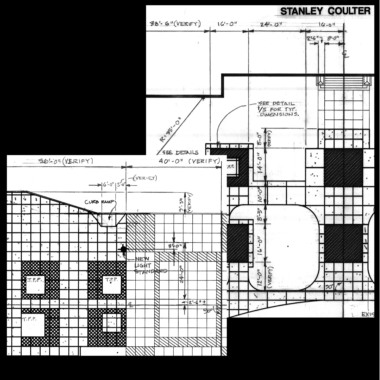
Figure 14. Dimension lines and distances.

The coordinate, or grid system is a comprehensive method of dimensioning. It sets up an imaginary rectilinear grid, usually with a north-south and east-west orientation. Proposed elements are located based on (X,Y) coordinates on the grid. The X and Y values are dimensions from two perpendicular base lines. The intersection of the two base lines is the origin, or (0,0) point on the grid. You can think of the grid method as if a piece of graph paper was laid over the site with, generally, the lower left hand (south- west) corner being the origin.(Figure 15)

Sample Layout - Dimension plan utilizing a grid with baselines A & B.

Figure 15. Sample Layout – Dimension plan utilizing a grid with baselines A & B.

Stationing is another system of layout used for uniform linear site features such as roads, trails, or utility lines. A centerline is defined and measurements are indicated in 100-foot increments along its length. Layout by stationing requires technical surveying techniques and is seldom used in landscape planting projects.

In complex projects, a combination of layout systems may be used. Overall site layout may be based on coordinates, with secondary or more localized elements located via linear dimensioning, offsets, or center points and radii.

Grading Plan

The grading plan deals with the vertical and horizontal dimensions of a site; that is the shape of the land surface. This is commonly referred to as topography. The plan shows the location of proposed site elements and the vertical form (elevation) of all the land surfaces relative to a fixed point of known elevation. (See Figure 2)

Just as with layout dimensions, elevations are expressed relative to a known point. In grading, it is a point of defined elevation. This known point is called a reference point, datum or benchmark.(Figure 16) It may be a permanently constructed element just for the purpose of defining elevation (a brass plate in concrete set in the ground) or it may be as simple as a corner of a pavement or curb. It should be clearly called out on the grading plan and readily identifiable on the site. All elevations, or grades, on the site are figured relative to the elevation of the benchmark.

Example of Benchmark on grading plan drawing.

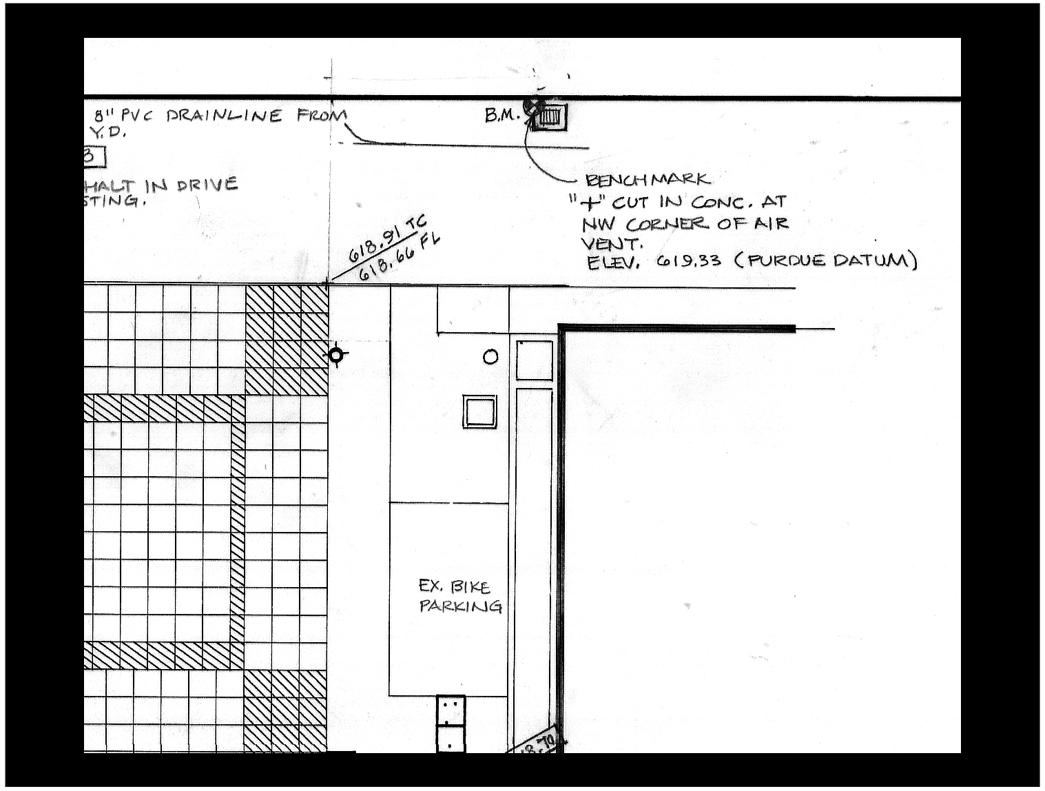
Figure 16. Example of Benchmark on grading plan drawing.

Elevations, or topography are shown on a grading plan either with topographic lines or as individual points. Often, both are used on the same plan. Topographic lines are lines that connect points of equal elevation at even intervals above the reference point or datum.

In landscape work, one foot is the most common topographic interval. Thus, there is a line for each one foot of elevation. Individual points are called out by their precise elevation, usually to an accuracy of one one-hundredth of a foot. These are called spot elevations. (Figure 17)

Example of spot elevations on grading plan drawing.

Figure 17. Example of spot elevations on grading plan drawing.

Grading involves making changes to an existing land surface resulting in an altered one. That may mean raising the grade or elevation (a fill) or lowering the grade or elevation (a cut). To show the necessary changes and illustrate how much soil must be added or removed, both existing and proposed topography is shown on a grading plan.

Typically, existing topography is shown by broken or dashed lines, while proposed topographic lines are solid. The elevation of each line is written next to the line, and always on the high, or “uphill” side. It is written so that the reader is looking up the slope when reading the elevation of the line.

Similarly, spot elevations are indicated as existing or proposed. Both are shown as numbers adjacent to a cross symbol (+) indicating the precise location of the elevation. A commonly used graphic technique shows a proposed spot elevation value in a box, while an existing spot elevation value has no box around it.

Individual plant symbols usually have a cross, a dot or an “x” symbol in the center indicating the actual location of the plant crown or main stem. They should be precise enough to allow the plant installer to use an appropriate

Planting Plan

The planting plan shows all the plants that are to be installed on a project. Symbols are used to represent different types of plants.

Locations are shown in the manner of a layout drawing, but dimensions are omitted. The plant list, a table summarizing information for all the plants shown on the plan, is typically presented on the sheet with the planting plan drawing (Figure 3).

Some typical symbols used on planting plans.

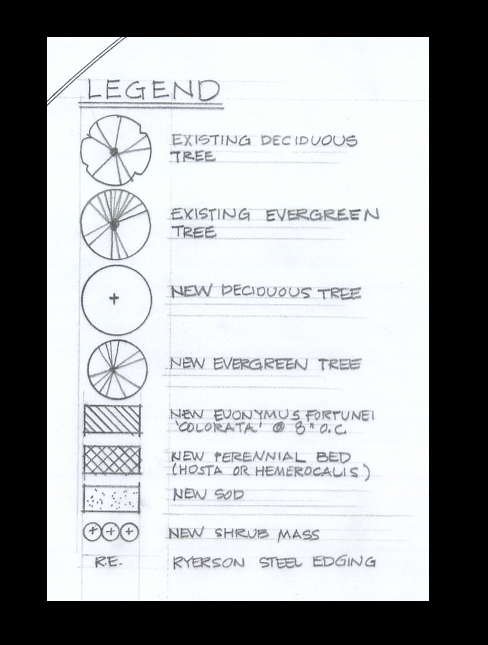
Figure 18. Some typical symbols used on planting plans.

Many graphic symbols and devices are used to represent plants on a planting plan. Symbol size is usually representative of the size the plant will reach after several years in the landscape, not fully mature size. Large and medium-size plants are shown individually, while small plants used to create a mass effect are often shown as a uniform mass or group. A graphic texture may be used to define such an area. When mass planting areas are illustrated, information must be supplied for plant spacing and arrangement (rectangular grid, triangular grid, etc.) within the mass. Figure 18 shows some examples of symbols used to illustrate plants.

Individual plant symbols usually have a cross, a dot or an “x” symbol in the center indicating the actual location of the plant crown or main stem.  They should be precise enough to allow the plant installer to use an appropriate ruler (architect’s or engineer’s scale) to measure the correct location for each plant from the drawing. A symbol on a planting plan in a contract document set should never be so “artsy” that the precise intended planting location is obscured.

Labeling on a planting plan should be very thorough! There should be no guessing as to which plants are which. Every plant should have a label (either the plant name or code that relates to the plant list) attached to it directly, or it should be graphically connected to other similar plants in a group with the group clearly labeled. The best labels are those that indicate the quantity of plants covered by that specific label, as well as the plant name.

A typical Plant List from a planting plan drawing.

Figure 19. A typical Plant List from a planting plan drawing.

The plant list is a complete table of information about all the plants represented on the planting plan drawing.(Figure 19) For every type and size of plant used in the design, it gives a complete, accurate scientific name in correct form with the quantity, plant size and root condition required. A common name for each plant is generally included, too, although primary use should be made of the scientific name. There may be notes or comments about certain plants included in the plant list to further explain the design intent.

Complex projects with little room for labeling on the plan may require that a coding system be used to relate the plants on the plant list to the labels on the drawing.  Such coding may be necessary, but is usually difficult to use. Extra care should be exercised when reading planting plans employing a code system.

Plant quantities shown on the planting plan, taken together, should match the total of the same plants listed on the plant list. However, such is not always the case. Mistakes happen. It is generally held that the number of plants shown on the drawing is the correct one and is the actual number implied in the contract. Thus, it is not enough for a contractor to look only at the plant list when preparing a cost estimate, ordering stock, or when pulling plants to bring to a job site.  The drawing itself must be studied.

Detail Drawings

A detail drawing is a way of communicating how to install or build something when such communication is most successfully accomplished using a picture rather than text. A detail is drawn at a scale that allows every detail of construction or planting to be fully illustrated. Details are often cross section views (Figure 20) but may be “blow-ups” of plan views, too. (Figure 21) Elevation drawings are occasionally used in details (Figure 22) as are, rarely, perspective views.(Figure 23) Multiple detail drawings are generally presented on one sheet, or may be added in available space on plan view sheets (see Figure 4, above). Often planting details are included on the planting plan drawing. (See Figure 3, above)

Sample cross-section details.

Figure 20. Sample cross-section details.

Sample plan view details.

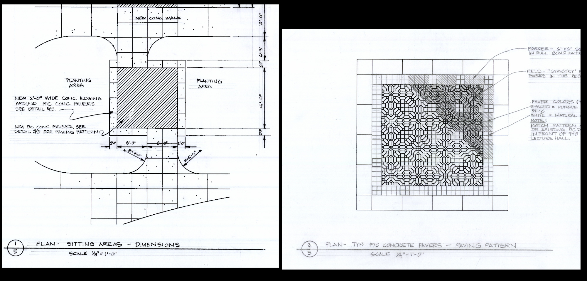
Figure 21. Sample plan view details.

Sample elevation detail.

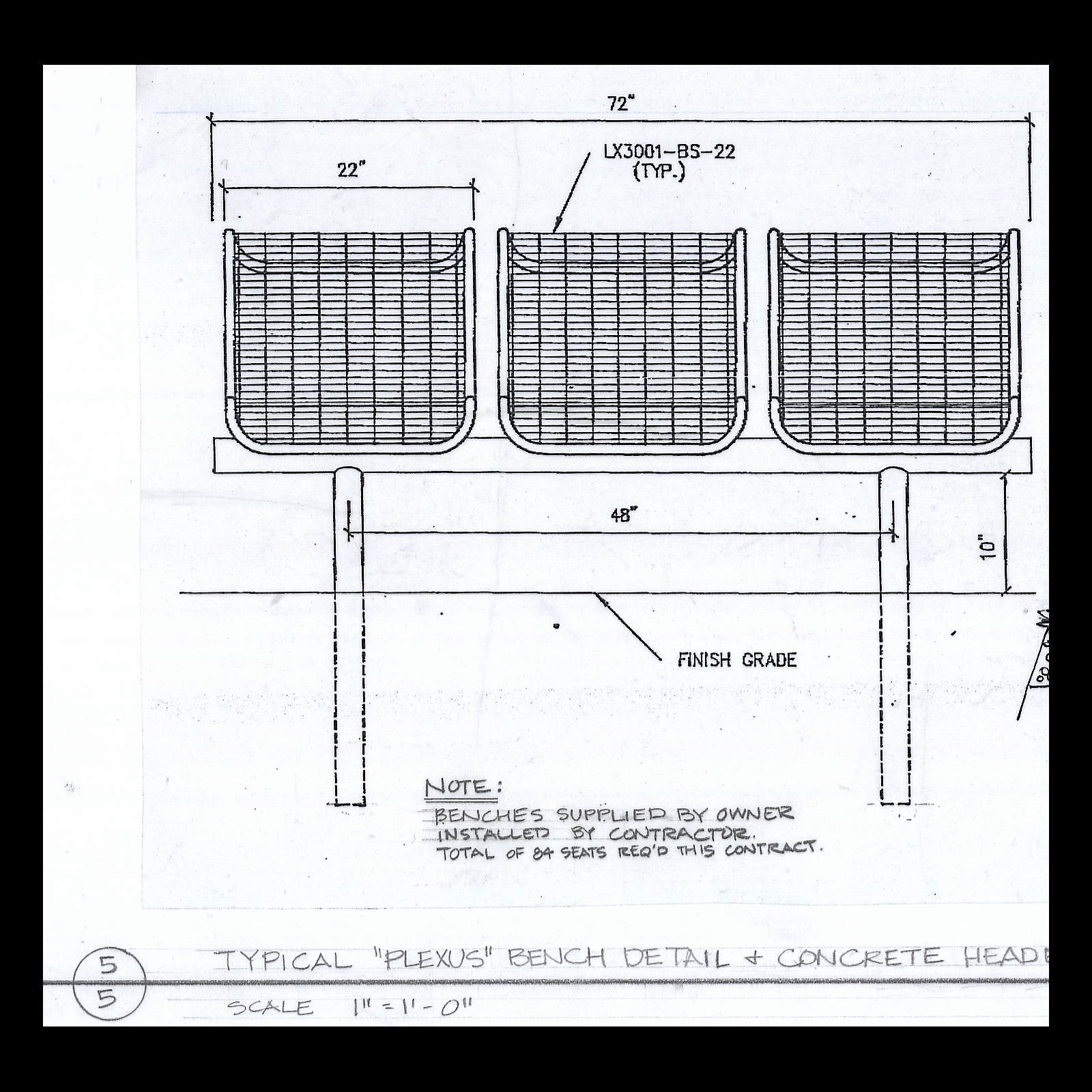
Figure 22. Sample elevation detail.

Sample perspective detail.

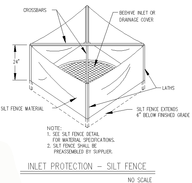
Figure 23. Sample perspective detail.

Summary

Contract documents are a means for owners and designers to communicate with those who actually build, plant and create landscapes. Knowing where to find and how to read and interpret information in contract document sets is fundamental for the successful landscape industry professional.


For Additional Reading

  •  Poage, W. 1991. The Building Professional’s Guide to Contract Documents, 3rd. ed.. R. S. Means, Kingston, MA.
  • Collier, K. 2001. Construction Contracts, 3rd. ed. Prentice Hall, New York.
  • Carpenter, P. & T. Walker. 1990. Plants in the Landscape. Waveland Press, Prospect Heights, IL.
  • O’Brien, J. 1998. Construction Change Orders: Impact, Avoidance, and Documentation. McGraw-Hill Professional, New York.
  • Harris, C. with N. Dines & K. Brown (eds.). 1997. Time-Saver Standards for Landscape Architecture, 2nd. Ed. McGraw-Hill Professional; New York.
  • 2000. Landscape Specification Guidelines, 5th Ed. Landscape Contractors Association of MD, DC, VA

  1. Typical written text documents that are in the contract document sets include:
    1. Invitation to bid
    2. List of drawings
    3. Affidavits
    4. All of the above
  2. (True or False): The existing conditions of the illustration documents include all information except underground utilities.
  3. What are types of technical specifications? (Select all that apply)
    1. Descriptive
    2. Performance
    3. Expedited
    4. Proprietary
  4. (True or False): The side view of a drawing is called an elevation view.
  5. What is the purpose of a layout plan?
    1. Vertical elements of structures
    2. Horizontal elements of structures
    3. Vertical elements of design
    4. Horizontal elements of design
  6. What information is typically provided on the plant list?
    1. Locations
    2. Size
    3. Quantity
    4. All of the above
  7. What information is typically provided on the plant list?
    1. Locations
    2. Size
    3. Quantity
    4. All of the above
  8. To understand the existing and proposed elevations on a grading plan, you begin by locating and measuring from what?
    1. Reference point
    2. Center point
    3. Rally point
  9. A grading plan addresses:
    1. Irrigation
    2. Plant locations
    3. Topography
    4. Specifications of materials
  10. There are many documents contained in a set of Specifications. Which document is most directly related to the work done by those who build the landscape and install the plants?
    1. Grading
    2. Planting
    3. Demolition
    4. Layout
    1. D
    2. False
    3. A, B, and D
    4. True
    5. B
    6. D
    7. D
    8. A
    9. C
    10. B

Share This Article
Disclaimer: Reference to products is not intended to be an endorsement to the exclusion of others which may have similar uses. Any person using products listed in these articles assumes full responsibility for their use in accordance with current directions of the manufacturer.
Indiana Accredited Horticulturist Program - Horticulture & Landscape Architecture, 625 Agriculture Mall, West Lafayette, IN 47907

© 2024 Purdue University | An equal access/equal opportunity university | Copyright Complaints | Maintained by Indiana Accredited Horticulturist Program

If you have trouble accessing this page because of a disability, please contact Indiana Accredited Horticulturist Program at daniel38@purdue.edu | Accessibility Resources