Purdue-P Web Simulator
Visit the blog for more tips on how to use the simulator.
Click on each tab to learn more about these p-circuits.
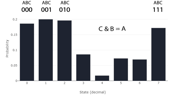
The Probabilistic Spin Logic algorithm is capable of emulating various Boolean logic gates, like the AND gate. By encoding a gate's truth table into a J-matrix, the p-circuit can be made to prefer only the states that appear in its truth table. If certain p-bits within the circuit are prevented from flipping naturally, such as the output to an AND gate, the other p-bits will adjust to ensure the system continues to observe only states in its truth table. The "AND gate" option will load in the parameters for an AND gate.
AND Gate Histogram
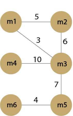
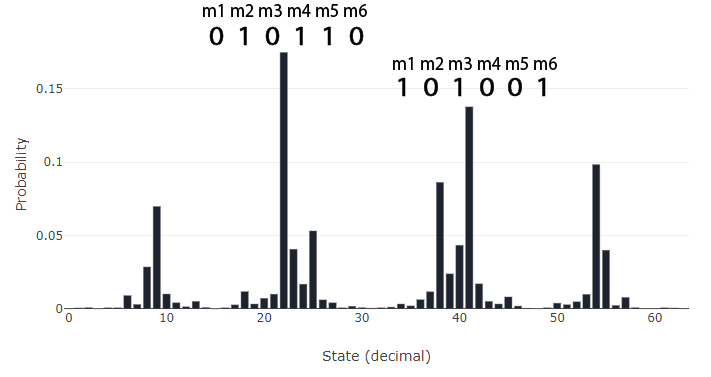
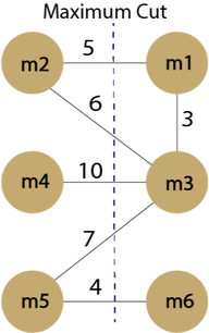
Maximum Cut is an NP problem that is commonly solved in VLSI design. The J-matrix that encodes the max-cut problem is simply the adjacency matrix of some graph. This ensures that the p-bits connected by the largest weights are pushed to opposite states, while p-bits connected by small weights are given less precedence. The final state puts each p-bit in one of two groups {1, 0}. The histogram reveals the most occupied states of the system, which give the "cut" through the graph that intersects the largest combined weight. If the system is annealed properly, it should converge to some state that solves the max-cut problem.
Input Graph
Histogram of p-bit states
Max. Cut
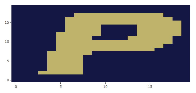
For large networks, the ground state of a J-matrix can be encoded using some image, essentially a custom ground state. The J-matrix will contain -1 connections between pixels of differing colors, and +1 weights for same colored pixels. In this case, a 20x20 pixel P has been programmed into a 400x400 dimension J-matrix (400 p-bits). This network of 400 p-bits is slowly cooled until the states lock into a single position. Done slowly, the p-bits should cool into the letter P, as shown below. The final state heat map displays the final state. Selecting "Anneal to image" will load the parameters of this problem into the simulator.
Final p-bit State Heatmap
In a digital age where safety and privacy amount to the strength of encryption algorithms,
factorization has become increasingly relevant. Purdue-p offers a novel method of
factorization that has to do with running a multiplier circuit in reverse. By pinning the
output bits of a multiplier network, we can watch the input p-bits fluctuate to the correct
inputs that multiply to give us that output.
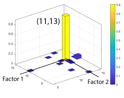
This example loads an 8-bit factorizer J and H into the simulator. The output is
pinned by setting the final 8 values of the H vector to + or – 10 (+10 pins to 0 and -10
pins
to 1). This biases those p-bits with a high enough value that they will not flip from their
initial state. To factorize 143 (this is pre-loaded) the last 8 bits have been set to [-10,
10, 10, 10, -10, -10, -10, -10], corresponding to [1,0,0,0,0,1,1,1,1] = 143. Try changing
the
last 8 bits to some other number and see if the factors turn out correct!
Histogram of p-bit states
Purdue-P Web Simulator

